Multimodality imaging system

a multi-modality imaging and imaging system technology, applied in the field of medical devices, can solve the problems of degrading the effect of diagnoses on patients, ensuring the correct image fusion,

Inactive Publication Date: 2008-04-03
SHENYANG NEUSOFT PAISITONG MEDICAL SYST
View PDF10 Cites 18 Cited by
  • Summary
  • Abstract
  • Description
  • Claims
  • Application Information

AI Technical Summary

Benefits of technology

[0005]It is an object of the present invention to provide a multimodality imaging system capable of assuring that a moving trajectory of a patient is uniform when the patient is scanned at different subsystems and that positions of the subsystems remain constant before and after maintenance of apparatuses of the system.

Problems solved by technology

As a result, it cannot be assured that the image fusion is correct, thus degrading the effect of the diagnoses on the patient.

Method used


Image

  • Multimodality imaging system
  • Multimodality imaging system
  • Multimodality imaging system

Examples


example 1

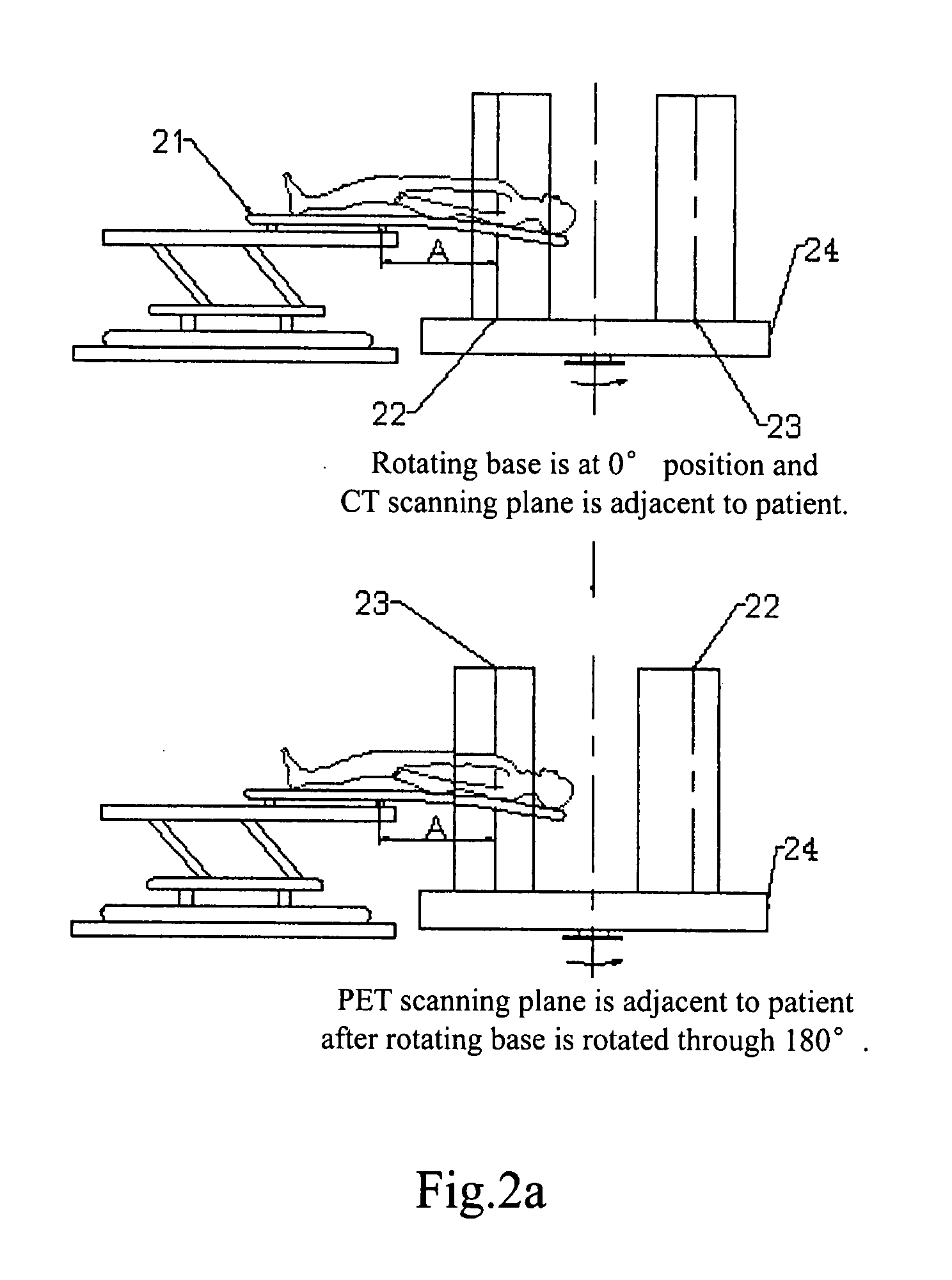
[0022]When a patient is to be scanned by the first imaging system CT 22′ as shown in FIG. 2a, the bed pallet 21 is located at an original position, the first imaging system CT 22′ is positioned adjacent to the bed pallet 21, and the second imaging system PET 23′ is positioned away from the bed pallet 21. The bed pallet 21 is moved forward so that the patient is sent to the scanning plane 22 of the first imaging system CT 22′. Firstly, the patient is scanned by the first imaging system CT 22′. After the patient has been scanned by the first imaging system CT 22′, the bed pallet 21 is moved back to the original position from a scanning position. Then, the first imaging system CT 22′ and the second imaging system PET 23′ rotate by or through 180° by an automatic control device, so that the second imaging system PET 23′ is positioned adjacent to the bed pallet 21 and the first imaging system CT 22′ is positioned away from the bed pallet 21. The bed pallet 21 is moved forward so that the...

example 2

[0023]When a patient is to be scanned by the first imaging system CT 22′ as shown in FIG. 2b, the bed pallet 21 is located at an original position, the first imaging system CT 22′ is positioned adjacent to the bed pallet 21, and the second imaging system PET 23′ is positioned away from the bed pallet 21. The bed pallet 21 is moved forward so that the patient is sent to the scanning plane 22 of the first imaging system CT 22′. Firstly, the patient is scanned by the first imaging system CT 22′. After the patient has been scanned by the first imaging system CT 22′, the bed pallet 21 is moved back to the original position from a scanning position. Then, the bed body rotates by or through 180° by an automatic control device, so that the second imaging system PET 23′ is positioned adjacent to the bed pallet 21 and the first imaging system CT 22′ is positioned away from the bed pallet 21. The bed pallet 21 is moved forward so that the patient is sent to the scanning plane 23 of the second ...


PUM


Abstract

A multimodality imaging system, comprising: a first imaging system for forming a first image; a second imaging system for forming a second image; and a rotating device on which the first imaging system and the second imaging system are fixed so that the first imaging system and the second imaging system are selectively rotated to a scanning position.

Description

BACKGROUND[0001]1. Field of the Invention[0002]The present invention relates to a medical apparatus, and particularly to a multimodality imaging system.[0003]2. Description of the Related Art[0004]When using a multimodality imaging system including medical apparatuses such as a CT (Computerized Tomography) apparatus, a MRI (Magnetic Resonance Imaging) apparatus, a PET (Positron Emission Tomography) apparatus, a SPECT (Single Photon Emission Computed Tomography) apparatus, in order to assure the effectiveness of synthesis of images formed by different apparatuses, it must be assured that an extent of deformation of a bed pallet is uniform at different detector positions when a patient on the bed pallet is scanned in the multimodality imaging system. Only when the extent of deformation is uniform, could it be assured that the image fusion is correct and positive to the effect of the diagnoses. When a patient is scanned with a PET apparatus 11 and a CT apparatus 12, an extent of deform...

Claims


Application Information

Patent Timeline
Patent Type & Authority Applications(United States)
IPC IPC(8): A61B5/00
CPCA61B6/032A61B6/5276A61B6/4417A61B6/0457A61B6/0487
Inventor ZHENG, QUANLUGAO, TIELI, JIADILIU, KAIYU, QINGZEXU, BAOWEIMU, HAITAOZHANG, QIZHIZHAO, XINGHUA
Owner SHENYANG NEUSOFT PAISITONG MEDICAL SYST
Why Eureka
Try Eureka