
System and method for optimized fuel efficiency and emission output of a diesel powered system

a technology of fuel efficiency and emission output, which is applied in the direction of electric devices, process and machine control, instruments, etc., can solve the problems of large variation in fuel consumption and/or emission output, difficult to achieve, and no further determination of actual emission output, etc., to minimize emission output

Inactive Publication Date: 2008-04-03
GENERAL ELECTRIC CO
View PDF44 Cites 38 Cited by
  • Summary
  • Abstract
  • Description
  • Claims
  • Application Information

AI Technical Summary

Benefits of technology

"The invention is a system, method, and computer software code for reducing emissions from a diesel powered system. The system determines the power needed to achieve a specific mission and calculates the emissions output based on that power. It then suggests using an alternative power level that results in less emissions output. This results in a more efficient and effective system with reduced emissions output."

Problems solved by technology

However, even with knowledge to assure safe operation, the operator cannot usually operate the locomotive so that the fuel consumption and emissions is minimized for each trip.
This is difficult to do since, as an example, the size and loading of trains vary, locomotives and their fuel / emissions characteristics are different, and weather and traffic conditions vary.
However, typically, there is no further determination made regarding the actual emission output while the train is in idle.
When operating a train, train operators typically call for the same notch settings when operating the train, which in turn may lead to a large variation in fuel consumption and / or emission output, such as, but not limited to, Nox, CO2, etc., depending on a number of locomotives powering the train.

Method used


Image

  • System and method for optimized fuel efficiency and emission output of a diesel powered system
  • System and method for optimized fuel efficiency and emission output of a diesel powered system
  • System and method for optimized fuel efficiency and emission output of a diesel powered system

Examples


Embodiment Construction

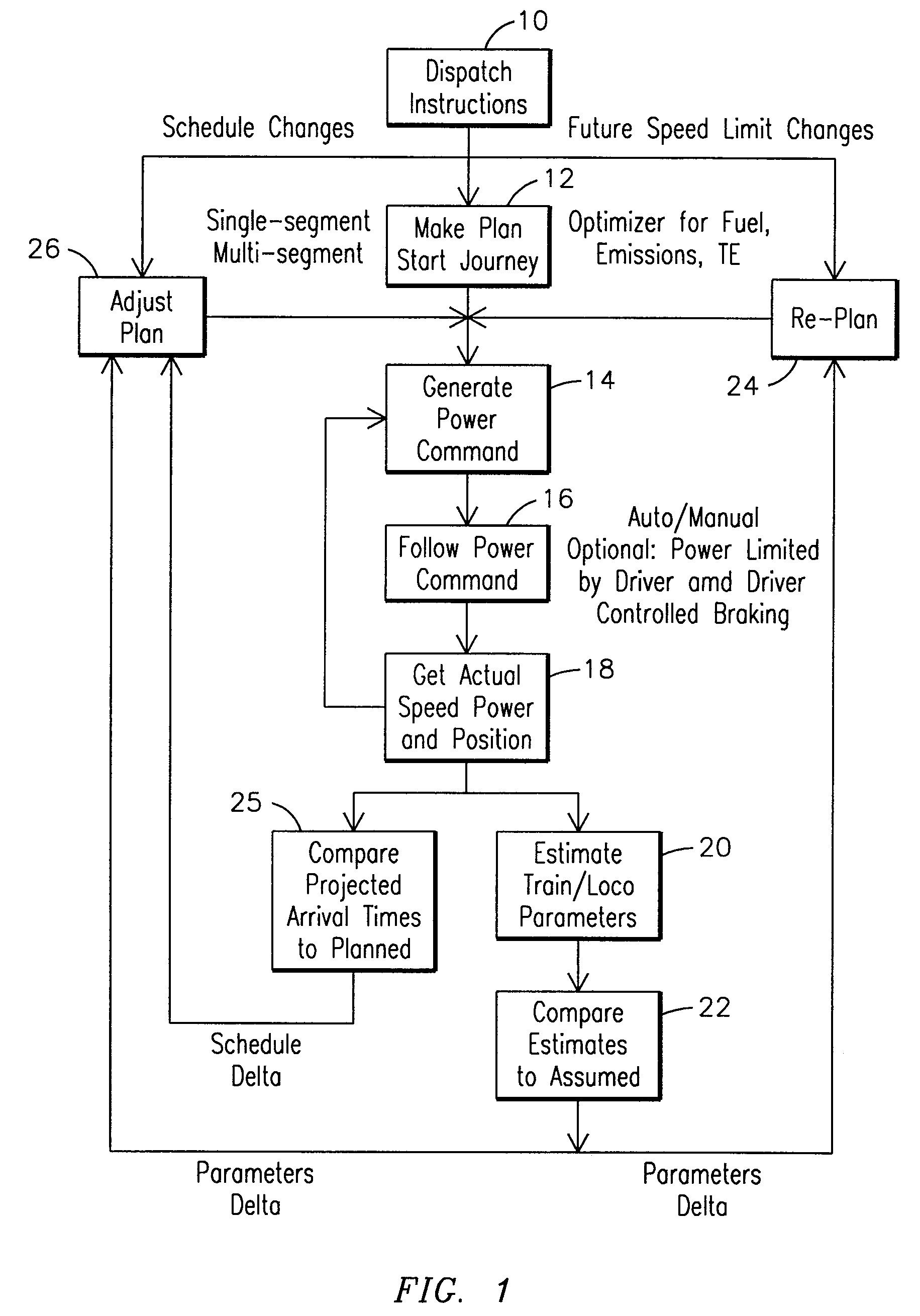
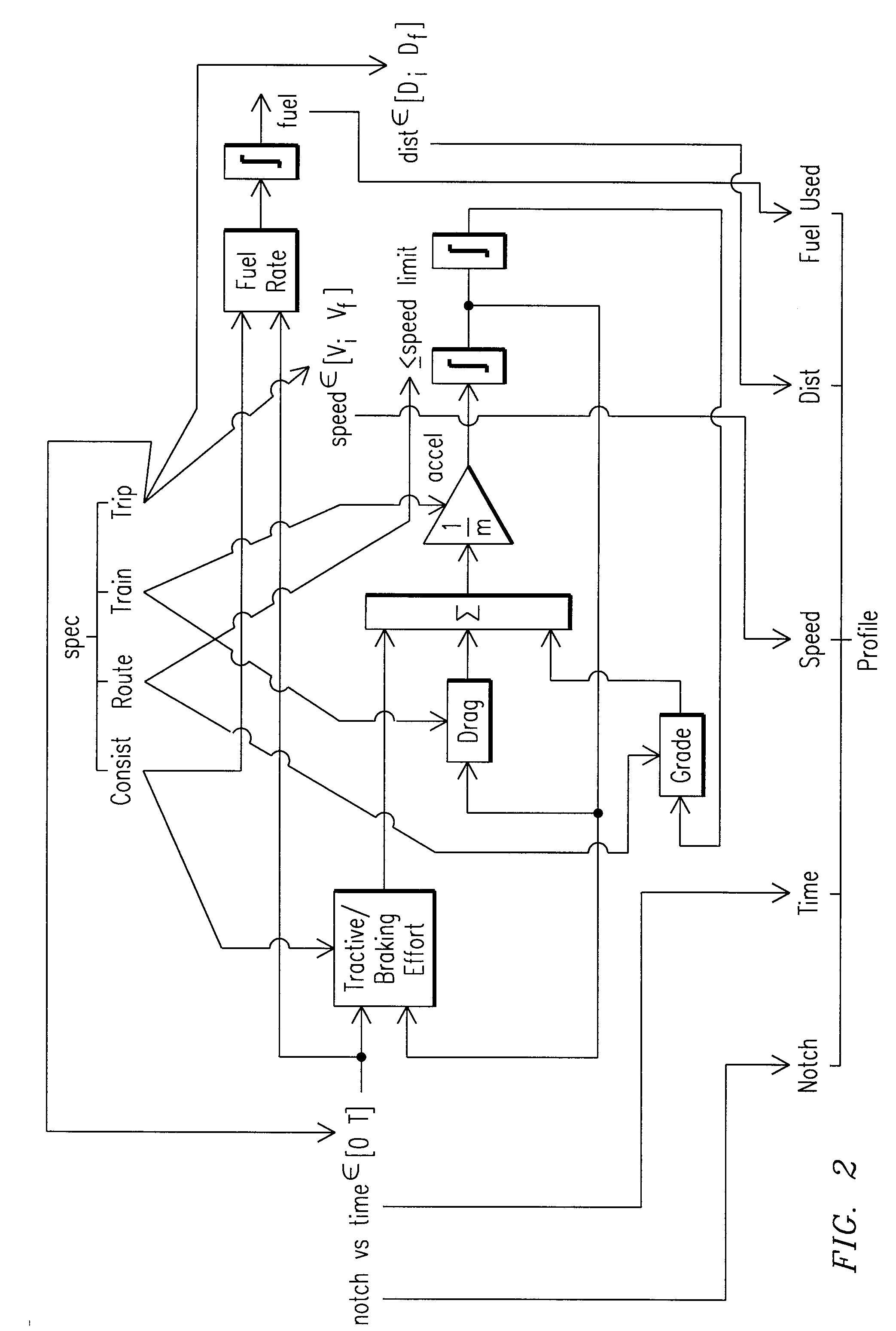
[0041]Reference will now be made in detail to the embodiments consistent with the invention, examples of which are illustrated in the accompanying drawings. Wherever possible, the same reference numerals used throughout the drawings refer to the same or like parts.

[0042]Though exemplary embodiments of the present invention are described with respect to rail vehicles, specifically trains and locomotives having diesel engines, exemplary embodiments of the invention are also applicable for other uses, such as but not limited to off-highway vehicles, marine vessels, and stationary units, each which may use a diesel engine. Towards this end, when discussing a specified mission, this includes a task or requirement to be performed by the diesel powered system. Therefore, with respect to railway, marine or off-highway vehicle applications this may refer to the movement of the system from a present location to a destination. In the case of stationary applications, such as but not limited to ...


PUM


Abstract

A method for minimizing emission output from a diesel powered system having at least one diesel-fueled power generating unit, the method including determining at least one power level required from the diesel powered system in order to accomplish a specified mission, determining an emission output based on the power level required, and using at least one other power level that results in a lower emission output wherein the overall resulting power is proximate the power required.

Description

CROSS-REFERENCE TO RELATED APPLICATIONS[0001]This application is a Continuation-In-Part of U.S. application Ser. No. 11 / 669,364 filed Jan. 31, 2007, which claims priority to U.S. Provisional Application No. 60 / 849,100 filed Oct. 2, 2006, and U.S. Provisional Application No. 60 / 850,885 filed Oct. 10, 2006. This application also claims priority to U.S. Provisional Application No. 60 / 894,039 filed Mar. 9, 2007, and U.S. Provisional Application No. 60 / 939,852.FIELD OF THE INVENTION[0002]This invention relates to a diesel powered system, such as a train, off highway vehicle, marine and / or stationary diesel powered system and, more particularly to a system, method, and computer software code for optimized fuel efficiency and emission output of the diesel powered system.BACKGROUND OF THE INVENTION[0003]Diesel powered systems such as, but not limited to, off-highway vehicles, marine diesel powered propulsion plants, stationary diesel powered system and rail vehicle systems, or trains, usual...

Claims


Application Information

Patent Timeline
Patent Type & Authority Applications(United States)
IPC IPC(8): G06F19/00
CPCB61L3/006B61L2205/04Y02T10/40B61L15/0058B61C1/00G05D1/00B61C5/00B61L2205/00
Inventor DAUM, WOLFGANGKUMAR, AJITH KUTTANNAIRDILLEN, ERICDUCHARME, DAVIDSHAFFER, GLENN ROBERTPRIMUS, ROYGRAY, STEVEN JAMESHALL, ED
Owner GENERAL ELECTRIC CO
Learn More