Utility vehicle drive system

a technology for driving systems and utility vehicles, applied in brake systems, electric energy vehicles, mechanical equipment, etc., can solve the problems of excessive delay for operators, long periods of idling while the vehicle is in motion, and the method of operation has not been introduced, so as to achieve low noise, low emission output, and low emission and noise output.

Active Publication Date: 2015-05-19
VOLTRA OY AB
View PDF6 Cites 6 Cited by
  • Summary
  • Abstract
  • Description
  • Claims
  • Application Information

AI Technical Summary

Benefits of technology

[0009]The invention allows the hydraulic motor in a hydrostatic branch of a power-split transmission to be driven by a source of pressurised fluid from the electrically-powered hydraulic pump. Advantageously, this allows the vehicle to be moved for a short period of time with low noise and low emission output. This is particularly advantageous when applied to an agricultural tractor for cattle shed operation.
[0010]By driving the hydraulic pump with an electric motor, various functions of the vehicle may also be operable whilst the engine is switched off. Therefore, low emission and noise output can be achieved. For example, the operator may drive into a cattle shed with a bale of feed on a front loader. Once in the shed the engine may be switched off whilst the operator (or someone else) unwraps the bale. The front loader can then be operated to tip the bale without starting the engine.
[0011]The vehicle may comprise one or more hydraulic pumps used for non-propulsive functions which may include, by way of example only, braking systems, linkage control systems and transmission ratio change systems. Each of these systems require a source of pressurised fluid to operate. In conventional utility vehicles, the operator is often required to wait after starting the engine for the auxiliary hydraulic systems to build up to working pressure. By driving the pumps with electric motors, a standby mode can be provided in which pressurised fluid is available to auxiliary functions when the engine is switched off. This avoids any waiting before moving the vehicle following starting of the engine.
[0013]In a preferred arrangement the vehicle further comprises a clutch between the engine output and the generator, and when in a tertiary propulsion mode, the clutch is disengaged, the engine is inactive, and the generator is operable as a motor to power the transmission and the propulsion means. In this case, the generator can operate as a motor when the engine is switched off so as to provide a low emission, low noise propulsion mode for a limited period of time.

Problems solved by technology

However, this method of operation has not been introduced in utility vehicles because repetitive stopping and starting of the engine would lead to excessive delay for the operator.
This results in long periods of idling whilst the vehicle is stationary.
Another drawback of internal combustion engines is the output noise levels.
In addition to the problems associated with operator comfort, noisy tractors can cause distress to cattle and other animals when operating nearby.

Method used


Image

  • Utility vehicle drive system
  • Utility vehicle drive system
  • Utility vehicle drive system

Examples


Embodiment Construction

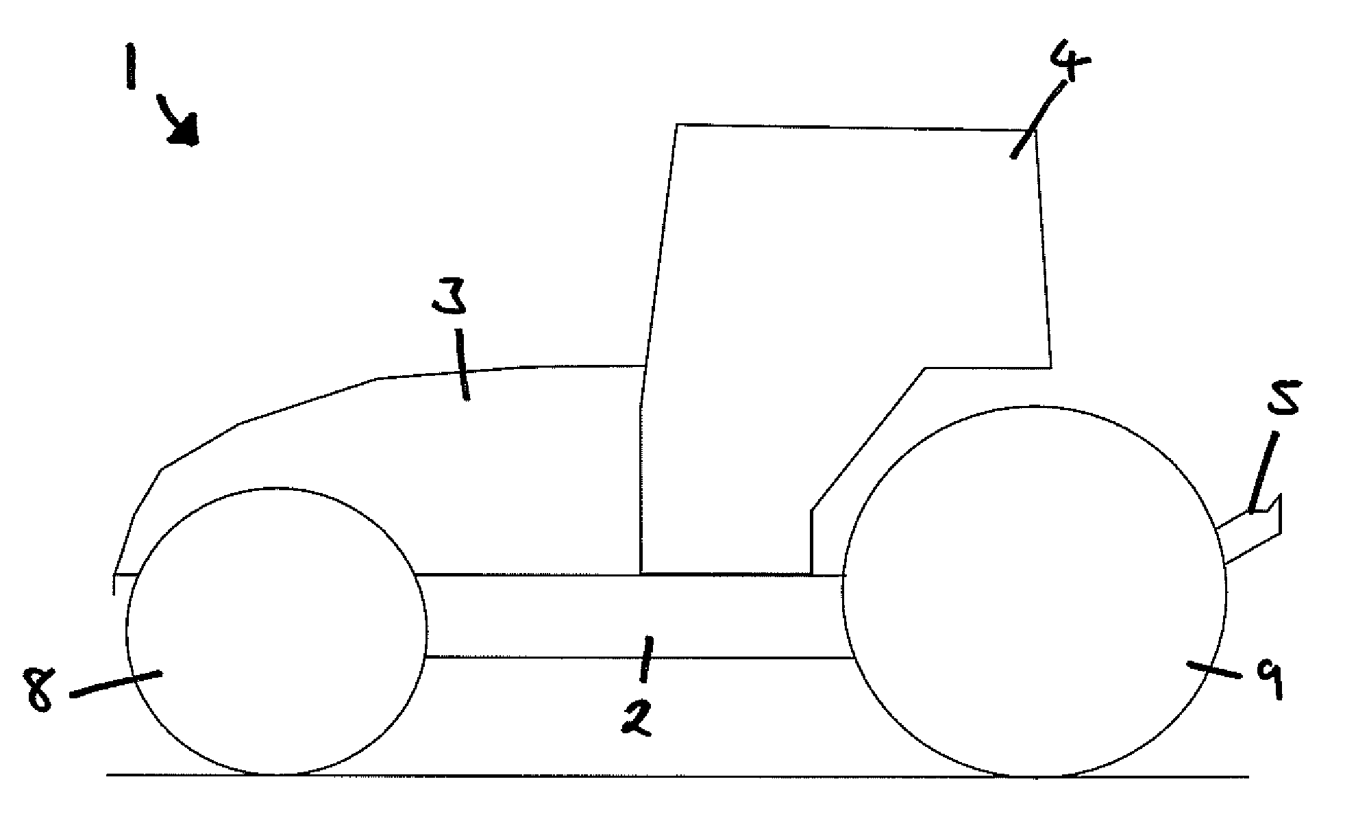
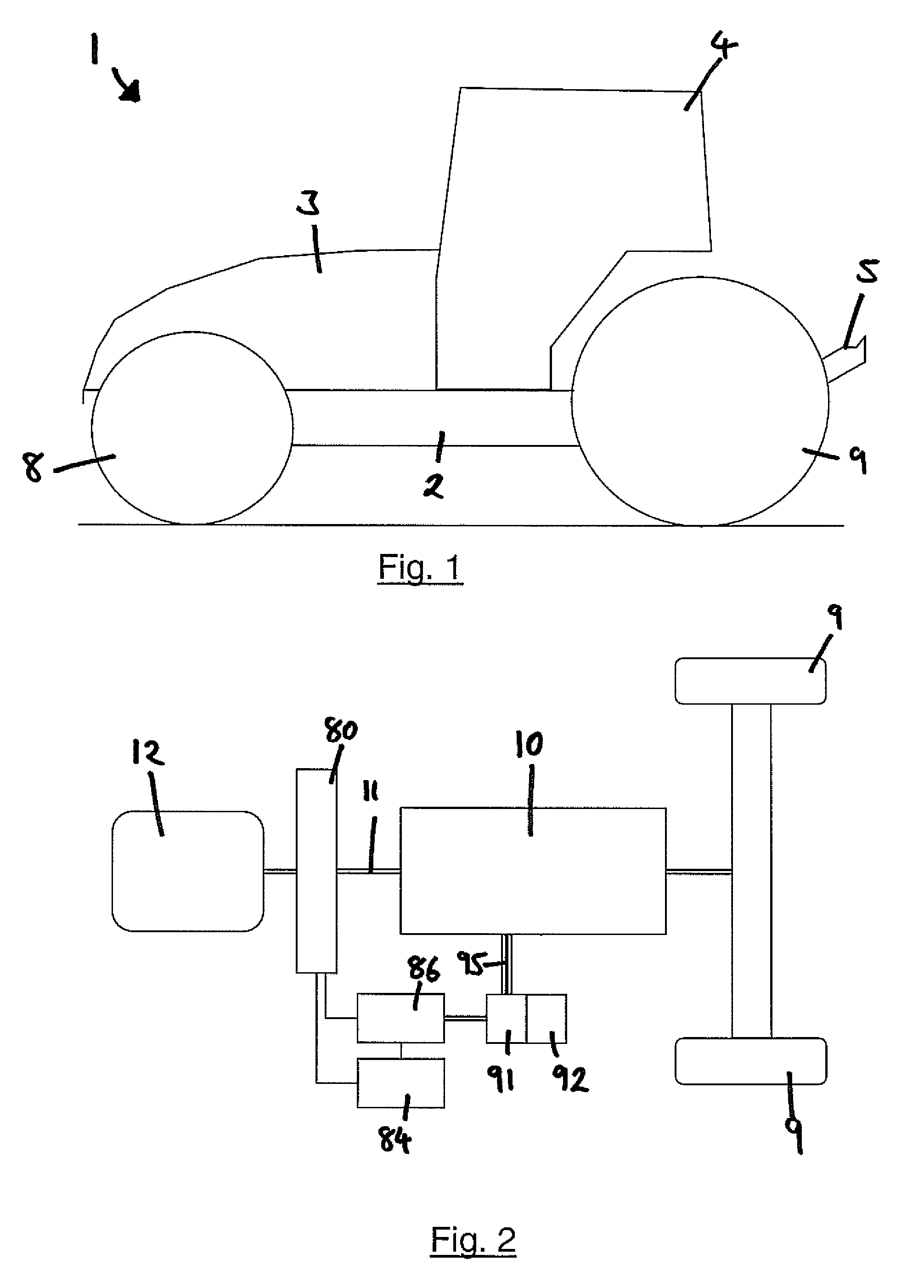
[0020]With reference to FIG. 1, an agricultural tractor 1 comprises a frame 2, a hood 3, a cab 4, rear linkage 5, front wheels 8 and rear wheels 9. FIG. 2 shows a drive system 10 which includes an engine 12 under the hood 3.

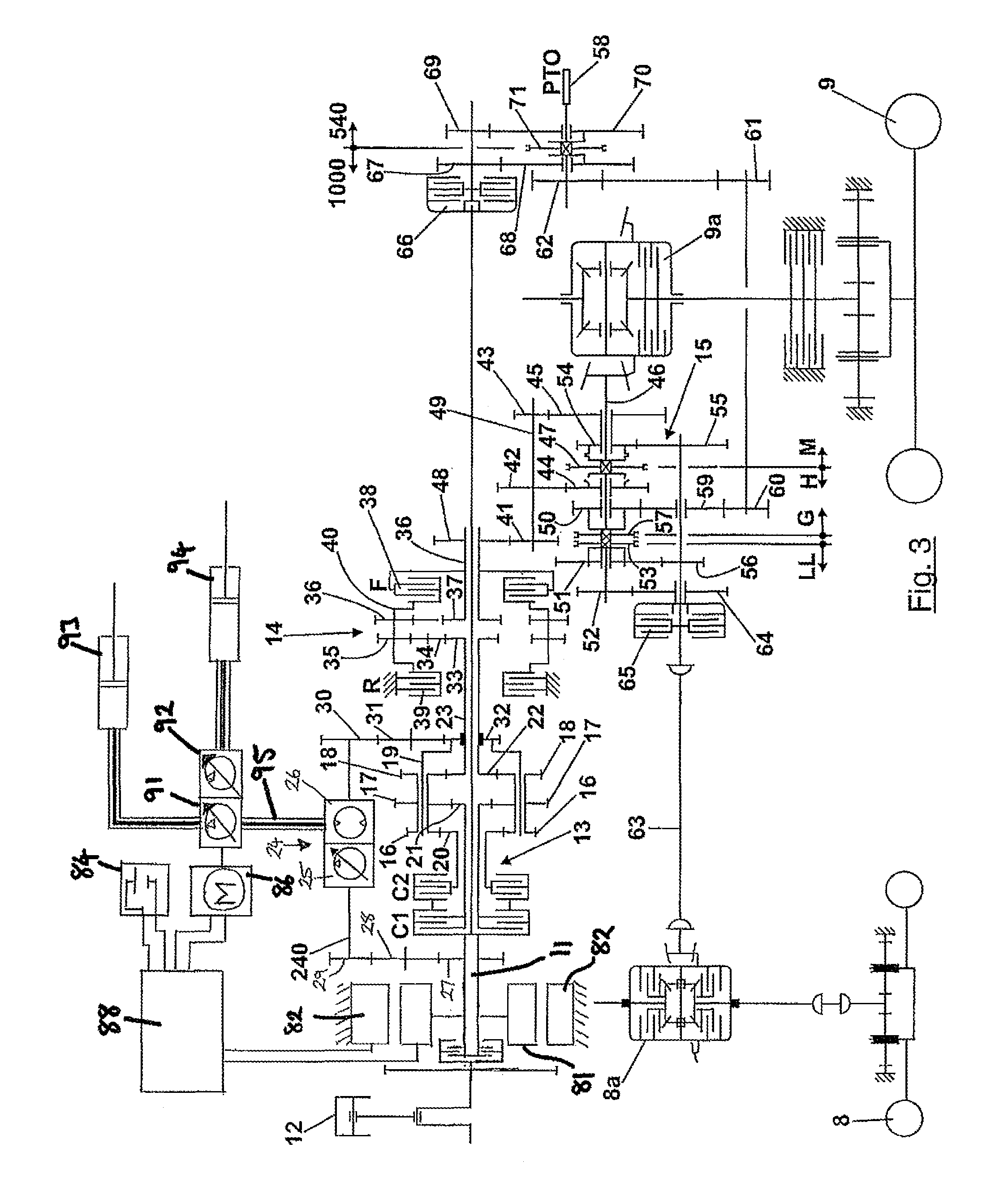
[0021]Referring to FIG. 3, a power-branched transmission 10 of a tractor has an input shaft 11 driven from an engine 12. The input shaft drives an epicyclic gear 13, a forward / reverse shuttle stage 14 and a further selectively engageable gear train 15 all in series. Gear train 15 in turn drives the front and rear wheels 8 and 9 via differentials 8a and 9a respectively.

[0022]The epicyclic gear 13 has three compound planets gears 16, 17, and 18 which rotate in unison at all times and are supported from a common carrier 19. Planets 16 and 17 engage sun gears 20 and 21 respectively which can be coupled with input shaft 11 via clutches C2 and C1 respectively. The third planet gear 18 engages a sun gear 22 mounted on an output shaft 23 of the epicyclic gear which is co...


PUM


Abstract

A hybrid drive system for a utility vehicle (1) which operates with an internal combustion engine (12) and an electrical generator (80), motor (86) and storage means (84). Auxiliary hydraulic functions (93,94) may be powered by the electric motor (86). An output of the engine (12) is mechanically coupled to a multi-ratio transmission (10) which has a hydrostatic driveline (24) and an output which is mechanically coupled to propulsion means. With the engine switched off, the electric motor powers a hydraulic pump (91) which generates pressurized fluid to operate auxiliary functions. In addition, the pressurized fluid may be exploited in a secondary propulsion mode to drive a hydraulic motor (92) in the hydrostatic transmission to propel the vehicle in a low emission, low noise output mode.

Description

CROSS-REFERENCE TO RELATED APPLICATION[0001]The present application claims the benefit of and priority from United Kingdom Application No. 1122219.7, filed Dec. 23, 2011, the entire disclosure of which is hereby incorporated by reference.FIELD OF INVENTION[0002]The invention relates to drive systems for utility vehicles such as agricultural tractors and plant machinery which include an internal combustion engine, an electrical generator and storage means, and at least one electrically driven hydraulic pump.BACKGROUND[0003]Today utility vehicles are powered by internal combustion engines. There is a continuing drive to reduce the emissions of such vehicles for environmental reasons. One way to reduce emissions in automobiles is to automatically switch off the engine when stationary, when in traffic for example. However, this method of operation has not been introduced in utility vehicles because repetitive stopping and starting of the engine would lead to excessive delay for the oper...

Claims


Application Information

Patent Timeline
Patent Type & Authority Patents(United States)
IPC IPC(8): F04B17/05B60K6/48B60K17/10B60K25/00B60T13/12B62D49/00
CPCF04B17/05B60K6/48B60K17/10B60T13/12B60K25/00B62D49/00B60Y2200/221Y02T10/6221B60W10/08B60W10/103B60W10/30B60W20/00B60K2025/005B60K6/442Y02T10/62
Inventor KURKINEN, KIMMOHANNUKAINEN, PETRI
Owner VOLTRA OY AB
Why Eureka
Try Eureka