
Scanning module

Inactive Publication Date: 2008-04-10
ASIA OPTICAL INT LTD
View PDF2 Cites 6 Cited by
  • Summary
  • Abstract
  • Description
  • Claims
  • Application Information

AI Technical Summary

Benefits of technology

[0009]The object of this invention is to provide a scanning module that has an improved scanning quality.
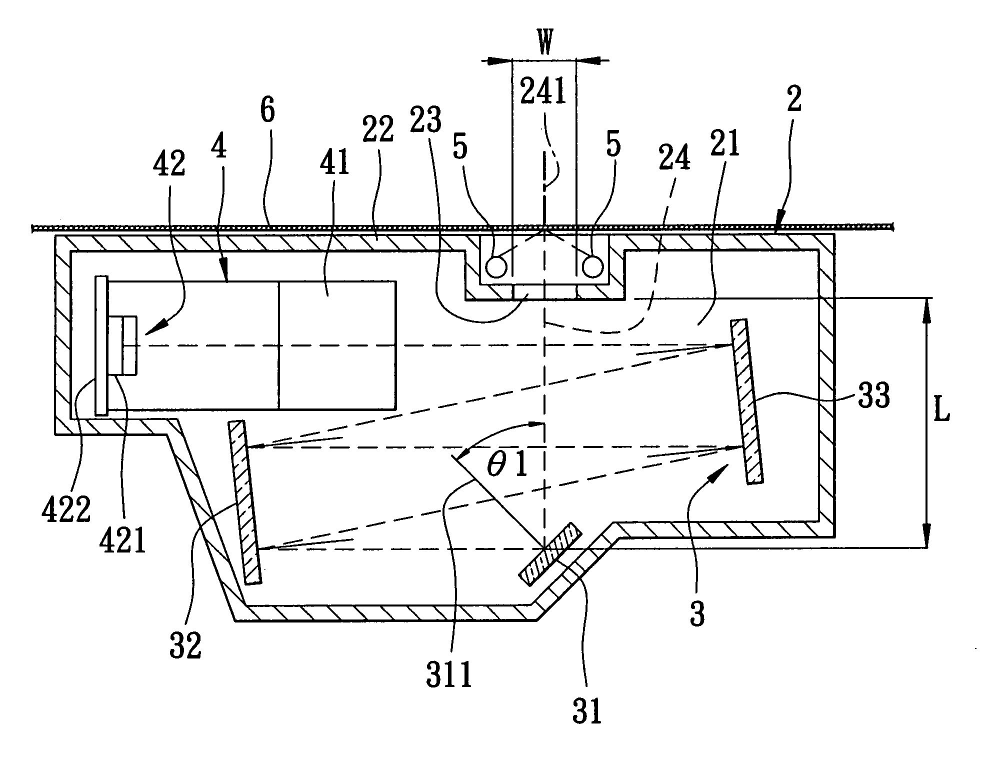
[0011]Since the angle formed between the incident axis and a normal line fo the first reflector is not smaller than 30 degrees, light beams reflected from the first reflector are generally horizontal. That is, light reflected from the first reflector cannot be transmitted back onto a document to be scanned. As such, the scanning quality of the scanning module is improved.

Problems solved by technology

That is, light reflected from the first reflector cannot be transmitted back onto a document to be scanned.

Method used


Image

  • Scanning module
  • Scanning module
  • Scanning module

Examples


Embodiment Construction

[0019]Before the present invention is described in greater detail in connection with the preferred embodiments, it should be noted that similar elements and structures are designated by like reference numbers throughout the entire disclosure.

[0020]Reffering to FIG. 3, the first preferred embodiment of a scanning module according to this invention includes a body 2, a reflecting unit 3, and an image capture unit 4. The body 2 includes a surrounding wall 22 and a reflecting chanber 21 disposed in the surrounding wall 22. The surrounding wall 22 is formed with an incident hole 23. Two light-emitting units 5 are located respectively to two opposite sides of the incident hole 23. When light is emitted from the light-emitting units 5 onto a document 6 to be scanned, which is disposed above the incident hole 23, it is reflected into the reflecting chamber 21 through the incident hole 23 along an incident axis 241 so as to form an incident light field 24. The incident light field 24 is perp...


PUM


Abstract

A scanning module includes a body, a reflecting unit, and an image capture unit. The body includes a reflecting chamber disposed in a surrounding wall. The surrounding wall is formed with an incident hole allowing an incident light field to be transmitted into the reflecting chamber therethrough along an incident axis. The reflecting unit is disposed within the reflecting chamber, and includes a first reflector for reflecting the incident light field, as well as second and third reflectors for reflecting light transmitted from the first reflector to the image capture unit. An angle formed between the incident axis and a normal line of the first reflector is not smaller than 30 degrees. The image capture unit is disposed nearer to the incident hole than the first reflector along a direction of the incident axis, and includes a lens, and a sensing member.

Description

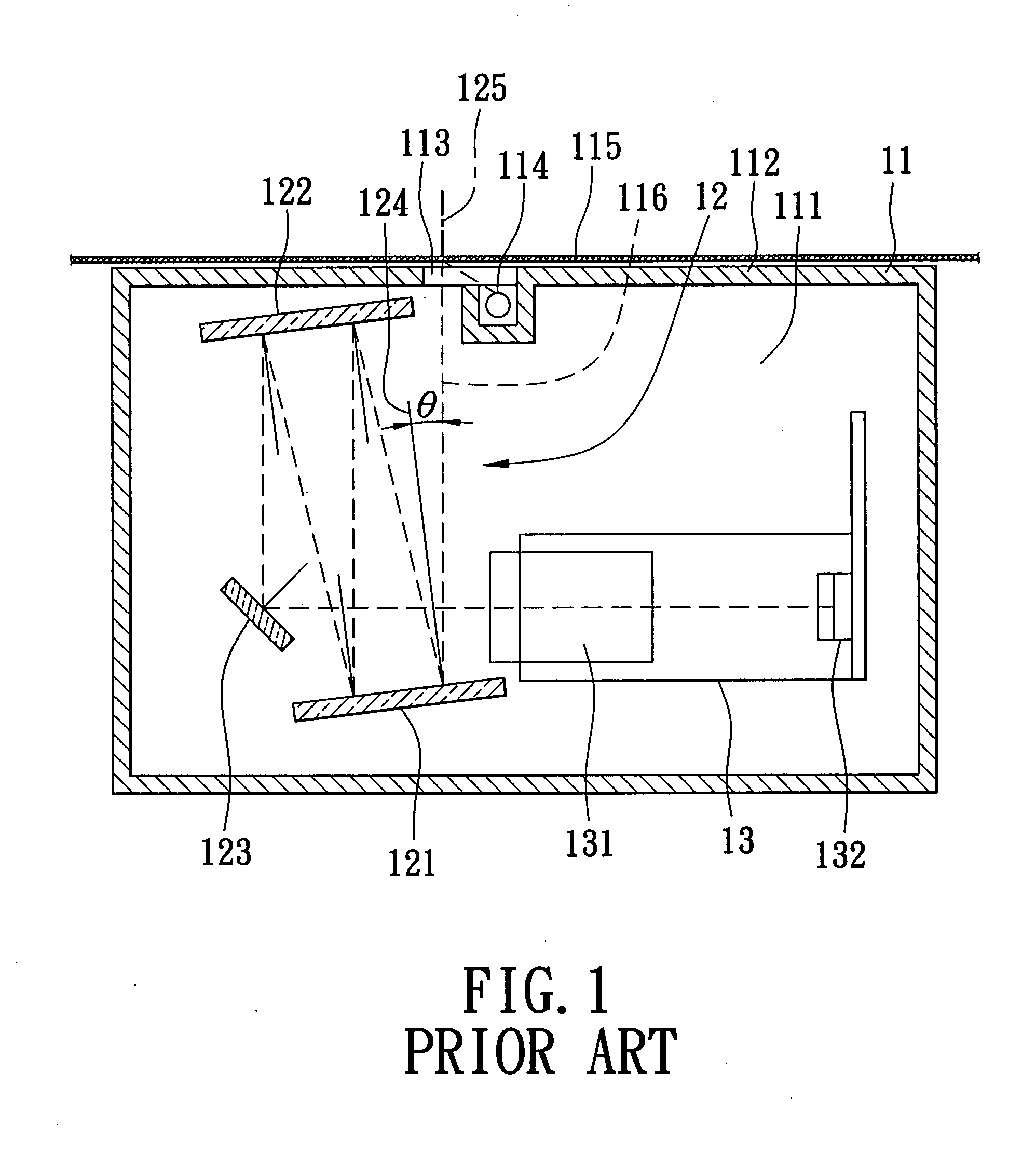
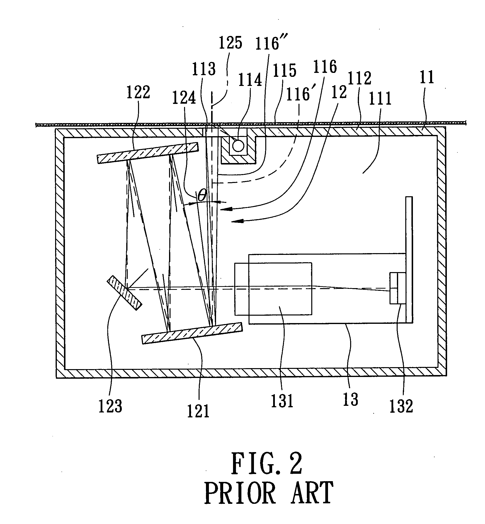
CROSS-REFERENCE TO RELATED APPLICATION [0001]This application claims priority of Taiwanese Application No. 095136894, filed on Oct. 4, 2006.BACKGROUND OF THE INVENTION [0002]1. Field of the Invention[0003]This invention relates to a scanning apparatus, and more particularly to a scanning module for scanning documents.[0004]2. Description of the Related Art[0005]Referring to FIG. 1, a conventional scanning module includes a body 11, as well as a light-reflecting unit 12 and an image capture unit 13 that are disposed within the body 11. The body 11 includes a reflecting chamber 111, and an incident hole 113 formed throught a top wall 112. Light is emitted from a light-emitting unit 114 onto a document to be scanned, and is reflected into the reflecting chamber 111 through the incident hole 113 along an incident axis 125 so as to form an incident light field 116.[0006]The reflecting unit 12 is disposed in the reflecing chamber 111, and includes a first reflecting mirror 121, a second r...

Claims


Application Information

Patent Timeline
IPC IPC(8): G02B5/08
CPCG02B26/0816H04N1/0281H04N1/195H04N2201/03145H04N2201/03116H04N2201/03137H04N2201/03112
Inventor LIN, HSIEN-CHICHANG, HENG-HSIANG
Owner ASIA OPTICAL INT LTD
Learn More