Method of MRI imaging using non-slice-selective, spatially tailored tip-up pulse

ip-up pulse technology, applied in the field of acquiring image data with a magnetic resonance imaging (mri) system, can solve the problems of limiting the application of bssfp, significant loss of snr and useful image contrast, and significant loss of bssfp imaging, so as to improve snr efficiency, prevent in-slice spin precession, and improve the effect of longitudinal magnetization

Active Publication Date: 2017-10-17
RGT UNIV OF MICHIGAN
View PDF5 Cites 3 Cited by
  • Summary
  • Abstract
  • Description
  • Claims
  • Application Information

AI Technical Summary

Benefits of technology

[0011]The invention advantageously interrupts precession of the in-slice spins in transverse plane (x, y) by applying the second pulse β({right arrow over (r)}) to rotate the in-slice spins toward the longitudinal axis (z). As such, longitudinal magnetization is rapidly and accurately reestablished before reapplication of the method of acquiring image data. Accordingly, SNR efficiency is improved and erroneous scans and repeats are minimized. Furthermore, the invention reduces cost by increasing initial scan quality thereby minimizing unnecessary additional scans.
[0012]The method further provides an MRI imaging technique which does not suffer from considerable signal loss and / or reduction in the SNR ratio. A significant amount of the NMR signal released by the in-slice spins is captured by realignment of the in-slice spins to the longitudinal axis (z) by the second pulse β({right arrow over (r)}). Additionally, the second pulse β({right arrow over (r)}) accurately tailors excitation of the spins to the local B0 inhomogeneity over the imaging volume. Thus, the effects of resonance frequency offset are mitigated thereby reducing signal variations due to resonance frequency offset.

Problems solved by technology

Unfortunately, bSSFP imaging suffers from considerable signal loss as a consequence of local B0 inhomogeneity.
Specifically, a significant loss of SNR and useful image contrast occurs in regions where the B0 frequency offset is an odd integer multiple of one-half of the inverse of the sequence repetition time, TR.
Consequently, dark bands may be present in the image, which is undesirable and limits the application of bSSFP.

Method used


Image

  • Method of MRI imaging using non-slice-selective, spatially tailored tip-up pulse
  • Method of MRI imaging using non-slice-selective, spatially tailored tip-up pulse
  • Method of MRI imaging using non-slice-selective, spatially tailored tip-up pulse

Examples


Embodiment Construction

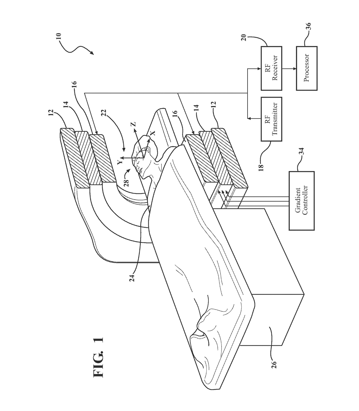
[0024]Referring to the Figures, wherein like numerals indicate corresponding parts throughout the several views, an MRI system is generally shown at 10 in FIG. 1. The MRI system 10 generally includes a field magnet 12, a set of gradient coils 14, an RF coil 16, an RF transmitter 18, and an RF receiver 20. The field magnet 12 has a coaxial cylindrical configuration and defines a bore 22 therein. An object 24, typically a human body, is disposed on a support 26 which is moveable within the bore 22. The gradient coils 14 and the RF coil 16 are disposed within the bore 22 of the field magnet 12.

[0025]The MRI system 10 conventionally images a region of interest (ROI) 28 of the object 24. For simplicity, the ROI 28 is shown as a human head in FIGS. 1 and 6. The ROI 28 is imaged according to a plurality of slabs or slices 30. Only one of the plurality of slices 30 is illustrated in FIG. 6 for simplicity. Each slice 30 is generally a planar region having any suitable thickness, such as 10 m...


PUM


Abstract

A method of acquiring image data with an MRI system from an object using a sequence of tip-down and tip-up RF pulses is described. A slice-selective first pulse α rotates the in-slice spins from the longitudinal axis (z) toward a transverse plane (x, y). Image data is acquired from the in-slice spins during a free precession interval (Tfree) in which the in-slice spins precess along the transverse plane (x, y). A spatially tailored, non-slice-selective second pulse β({right arrow over (r)}) is applied for rotating the in-slice spins from the transverse plane (x, y) to at least substantially along the longitudinal axis (z). A third pulse S may be applied to the in-slice and out-of-slice spins to eliminate (spoil) residual transverse signal from out-of-slice spins.

Description

CROSS REFERENCE TO RELATED APPLICATIONS[0001]The present application claims priority from U.S. Provisional Application Ser. No. 61 / 624,280, filed Apr. 14, 2012, which is herein incorporated by reference.GOVERNMENT LICENSE RIGHTS[0002]This invention was made with government support under EB012674 and NS058576 awarded by the National Institutes of Health. The government has certain rights in the invention.BACKGROUND OF THE INVENTION[0003]1. Field of the Invention[0004]The subject invention generally relates to a method of acquiring image data with a magnetic resonance imaging (MRI) system. More particularly, the invention relates to a method of acquiring image data using a sequence of radio frequency (RF) pulses for steady-state MRI.[0005]2. Description of the Related Art[0006]In magnetic resonance imaging (MRI), an MRI system includes a field magnet which is energized to produce a substantially homogeneous static magnetic (B0) field through a bore in which an object, typically a huma...

Claims


Application Information

Patent Timeline
Patent Type & Authority Patents(United States)
IPC IPC(8): G01V3/00G01R33/565G01R33/561G01R33/54
CPCG01R33/54G01R33/565G01R33/5614
Inventor NIELSEN, JON-FREDRIKYOON, DAEHYUNNOLL, DOUGLAS C.
Owner RGT UNIV OF MICHIGAN
Why Eureka
Try Eureka