Taper bore bearing assembly

a technology of bearings and components, applied in the direction of shafts, bearings, shaft assemblies, etc., can solve the problems of not being able to meet the tolerances, design does not permit deviations from the tolerances, and the removal is difficult, so as to achieve the effect of easy removal and/or cleaning of the bearing

Inactive Publication Date: 2008-04-10
FYH BEARING UNITS USA
View PDF9 Cites 3 Cited by
  • Summary
  • Abstract
  • Description
  • Claims
  • Application Information

AI Technical Summary

Benefits of technology

[0006]The present invention solves these and other problems by providing a taper bore bearing assembly that permits a wide range of variation in size of the rotating shaft in combination with a locking ring that permits easy removal and / or cleaning of the bearing.

Problems solved by technology

Two problems exist with this configuration.
However, the existing design does not permit deviations from set tolerances, as such deviations would prevent proper mechanical coupling.
However, the present configuration requires a tight mechanical fit, which can make removal difficult, especially after significant hours of operation in a potentially dirty or non-clean environment.
In certain applications, such as go-carts, a mechanic would prefer to clean the bearing assembly after use; however, in the existing configuration this is not possible without damaging the bearing assembly.

Method used


Image

  • Taper bore bearing assembly
  • Taper bore bearing assembly
  • Taper bore bearing assembly

Examples


Embodiment Construction

[0028]It is worthy to note that any reference herein to “one embodiment” or “an embodiment” means that a particular feature, structure, or characteristic described in connection with the embodiment is included in at least one embodiment of the invention. The appearances of the phrase “in one embodiment” in various places in the specification are not necessarily all referring to the same embodiment.

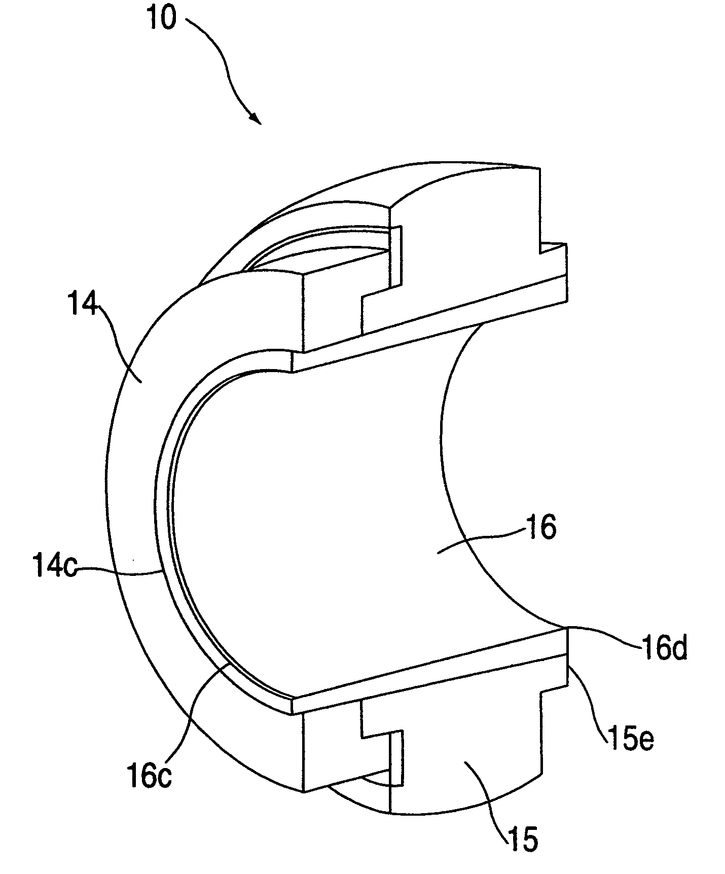
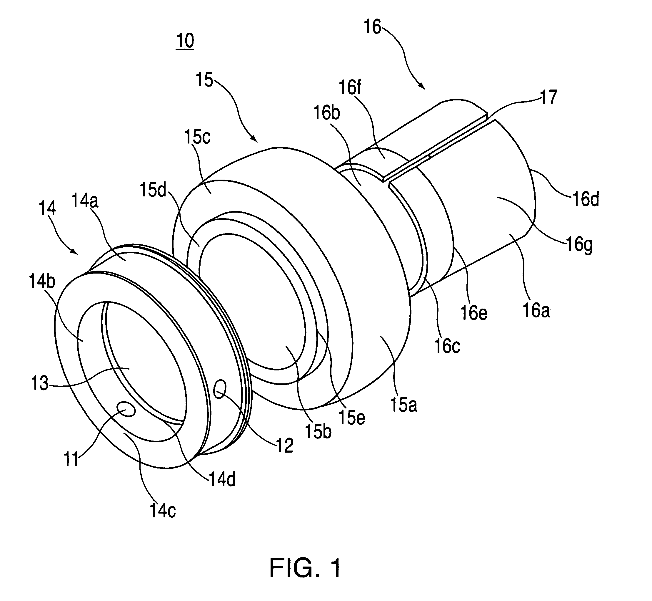
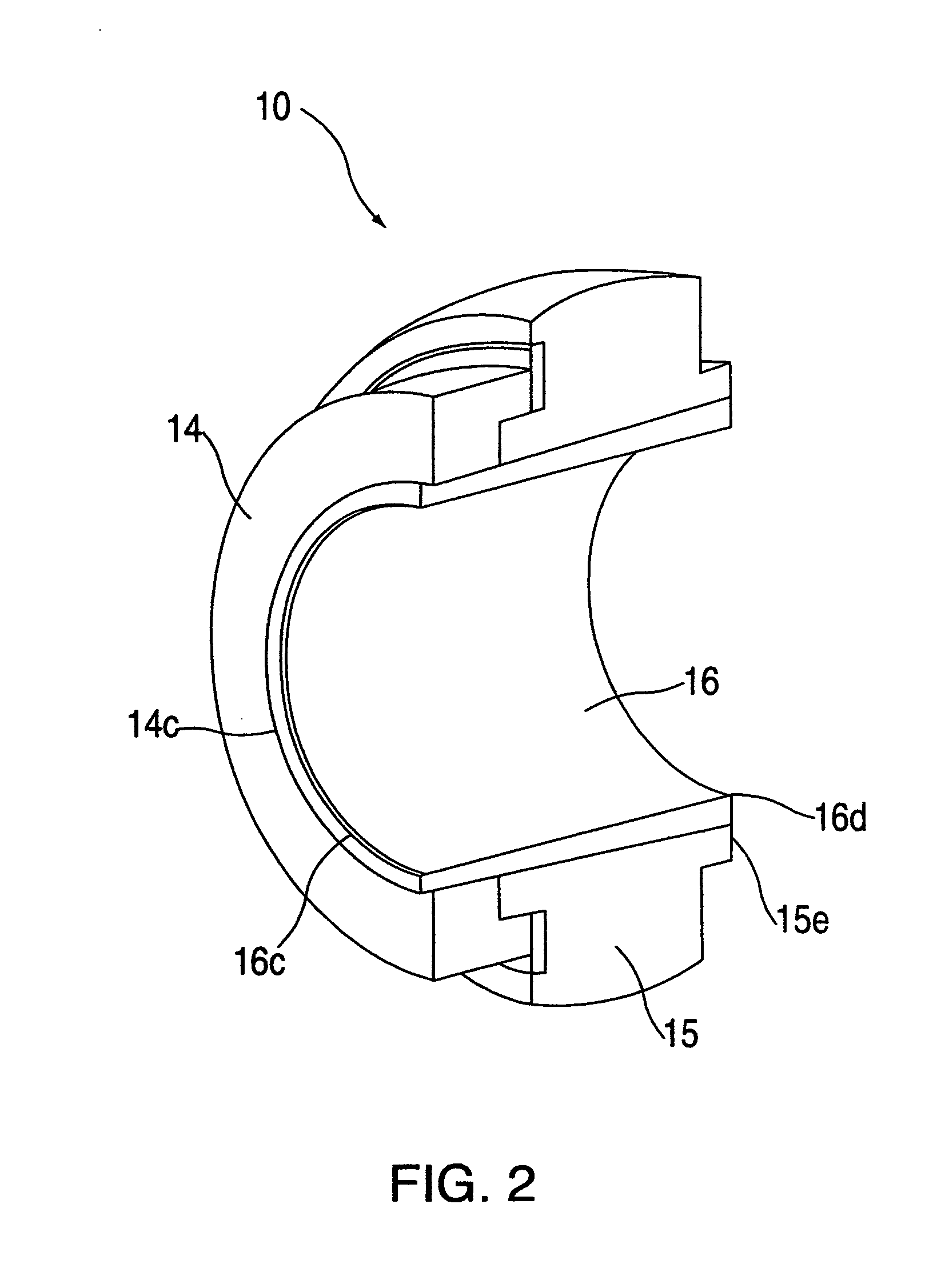
[0029]Referring to FIG. 1, shown therein is an exemplary embodiment 10 of the taper bore bearing assembly 10 of the present invention, which includes essentially three main components: an annular cylinder or ring 16, a rolling element bearing 15 and a locking ring 14. The taper bore bearing assembly 10 is designed to accept or be mechanically coupled to a rotatable shaft (not shown). Thus, the rotatable shaft rotates about a central axis of the taper bore bearing assembly 10. The rotatable shaft would be disposed in the hole 13 of the taper bore bearing assembly 10.

Annular Cylinder

[0030]Fo...


PUM


Abstract

A taper bore bearing assembly permits variability in diameter of the rotating shaft. An annular cylinder is mechanically coupled to the rotatable shaft and a bearing element is in turn mechanically coupled to the annular cylinder, which includes a tapered bore so that an interior diameter of the annular cylinder decreases from one end to the other. An inner race of the bearing element includes accepts the annular cylinder. The interior diameter of the inner race decreases from one end to the other. A locking ring locks the annular cylinder to the bearing element. Holes extend radially through the locking ring. A screw thread mechanically couples with the bearing assembly, which screw thread is inscribed on an interior surface of the locking ring. Cutout sections in the screw thread are formed by the holes. Setscrews disposed in the holes hold the locking ring in place. The setscrews include a foot to mechanically couple with the bearing assembly, which foot includes a portion of a screw thread that matches one of the cutout sections or holes of the screw thread.

Description

FIELD OF THE INVENTION[0001]The present invention relates generally to bearing assemblies and, in particular, to a bearing assembly for mechanically coupling to a rotary shaft or axle.BACKGROUND[0002]Rotary shafts are generally mounted such that their ends are rotatably mounted in respective rotary bearings, such as ball bearings, roller bearings, etc. For example, with reference to FIG. 4, a bearing 18 is mounted in an opening 14 of a bearing housing 10 of a conventional pillow block. A shaft end (not shown) would project through the bearing.[0003]Two problems exist with this configuration. First, the rotary shaft must be properly dimensioned to mechanically couple with the opening. However, the existing design does not permit deviations from set tolerances, as such deviations would prevent proper mechanical coupling.[0004]Moreover, the rotating shaft is preferably easily removed to permit maintenance on the apparatus. However, the present configuration requires a tight mechanical ...

Claims


Application Information

Patent Timeline
Patent Type & Authority Applications(United States)
IPC IPC(8): F16C43/00
CPCF16C35/02F16C23/04F16C2226/16
Inventor YAMASHITA, TORU
Owner FYH BEARING UNITS USA
Why Eureka
Try Eureka