
Device and method for monitoring video objects

a video object and device technology, applied in the field of methods for monitoring objects, can solve the problems of increasing the number of incorrect detections, not reducing the recognition effect of all object models, etc., and achieves the effects of reducing the number of models, facilitating detection, and increasing detection capability

Active Publication Date: 2015-03-10
ROBERT BOSCH GMBH
View PDF5 Cites 2 Cited by
  • Summary
  • Abstract
  • Description
  • Claims
  • Application Information

AI Technical Summary

Benefits of technology

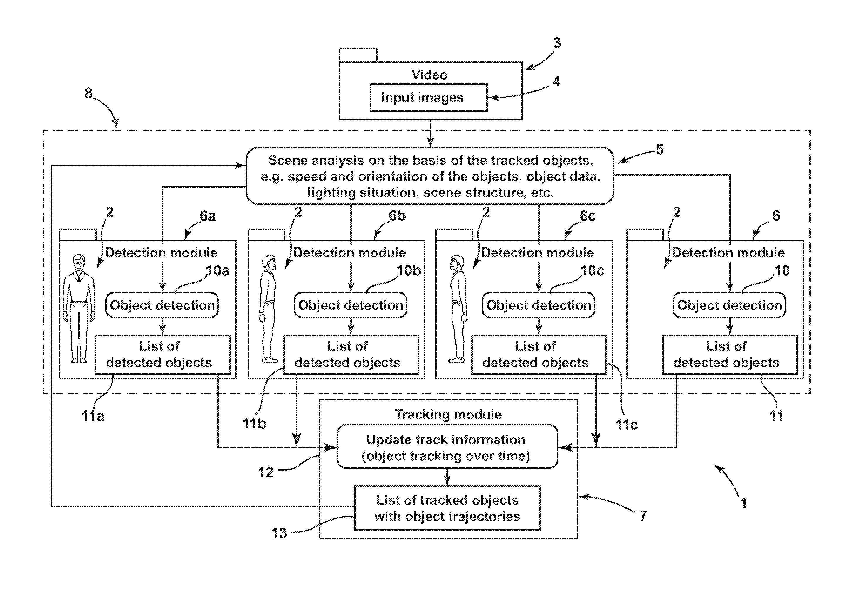
[0012]The feedback of information from the long-term observation of the object helps to determine the appropriate object model. Simple testing of all object models would not effectively increase the recognition results, since, owing to the higher total variance of the models, the number of incorrect detections would rise as well. Consequently, one advantage of the invention resides in the increase in the recognition capacity of the detector device. Furthermore, by virtue of the more specific object models, that is to say the models having a narrower variation range, in contrast to the more complex, more general models, that is to say the models having a wider variation range, the computing time can be reduced. Possible tracking parameters on the basis of which a subclass or a submodel is determined for the objects are, for example, the speed of the object, in which case a detector for moving objects can, for example, rapidly discard static image contents, or the orientation of the object, in order, for example, to detect different views of the object in a targeted manner. Possible scene parameters comprise the object density, which, for example, influences the number of expected objects per unit area, the expected object masking, the lighting situation, such as, for example, effects such as fog, light sources and the like, and the scene structure, such as, for example, knowledge of articles masking the objects.
[0013]One particularly preferred embodiment provides for detecting and / or tracking to be carried out in a model-based manner, that is to say to comprise selecting at least one of the models. For detecting and analogously also for tracking, from the predefined models at least one is selected. Preferably, the number of models is reduced further and further in the course of surveillance. In a first step, from the n models at least one model is not taken into account in a next step, such that then a maximum of only n−1 models are to be taken into account. This can be continued until only one model is to be taken into account. The models can be adapted with regard to their tracking parameter range and / or scene parameter range. Selecting is performed with the tracking parameters and / or scene parameters being taken into account. Precisely at the start of surveillances there are few data available about the objects to be monitored. The group boundaries for detecting the objects are defined in a correspondingly fuzzy manner. The more specific a model and the sharper the boundaries, the higher the detection capability. The objects to be detected are compared with the parameter ranges of the respective object models for detecting purposes. If the tracking parameters and scene parameters of an object fall within a parameter range of an object model, then this object model is used for detecting the object. In the next step, the recognized object can be tracked. Tracking parameters are determined again during tracking. Said tracking parameters are used during a renewed detection in order to further facilitate the detection. This is performed, in particular, by a new selection of an appropriate model having a smaller variation range and by changing the parameter ranges for the selection of the object models.
[0014]Preferably, detecting and / or selecting are / is carried out on the basis of predefined models. In this case, predefining the model comprises predefining models having different tracking parameter ranges and / or scene parameter ranges. Detecting and / or tracking comprise(s) selecting at least one of the models. In this case, selecting a model is carried out on the basis of tracking parameters and / or scene parameters. In the course of surveillance, an object to be monitored is detected and tracked more and more reliably, since a model appropriate to the object to be monitored is selected.
[0015]A further advantageous embodiment provides for selecting to comprise, at least at the beginning of a surveillance, adapting the parameter ranges, which in this way makes the models used for the detection more precise with regard to the object to be monitored. Accordingly, selecting and / or detecting comprise(s) altering the tracking parameter ranges and / or scene parameter ranges.
[0016]If an object cannot be assigned to exactly one model or submodel, then detecting is carried out on the basis of a plurality of models having different parameter ranges. By way of example, an object which moves diagonally upward toward the right is not reliably captured solely by the models for objects moving toward the right and objects moving upward. Rather, the object will fall within both parameter ranges, such that both models shall be used for reliable detection.
[0017]A further advantageous embodiment provides for the predefined object models to comprise both models having a large variation range and subordinate models having a smaller variation range. By way of example, a model having a large variation range can comprise the detection of persons in all views, whereas a subordinate model is specialized for the detection of persons with a specific direction of movement. This can be refined further and further, such that, by way of example, separate models with different leg positions or arm positions are predefined. At the beginning of the surveillance of an object, as yet little information about the object is present, and so the selection module for the detection will select an object model having a large variation range. If more precise tracking parameters are known in a later step, then by selecting a more specific object model having a smaller variation range the detection accuracy is increased, and an increase in detection speed is made possible.

Problems solved by technology

Simple testing of all object models would not effectively increase the recognition results, since, owing to the higher total variance of the models, the number of incorrect detections would rise as well.

Method used


Image

  • Device and method for monitoring video objects
  • Device and method for monitoring video objects

Examples


Embodiment Construction

[0022]The FIGURE shows schematically as a block diagram an apparatus 1 for monitoring objects, which apparatus implements a method according to the invention for monitoring objects. The apparatus 1 comprises an imaging unit, which is embodied as video system 3 and generates an image of the real surveillance region. The video system 3 generates different images 2 in short temporal succession, which images when joined together produce a scene. The images 2, present as input images 4, are analyzed in a detector device 8. The detector device 8 comprises detection modules 6 and a model selection module 5, which selects or chooses the detection modules 6, 6a, 6b, 6c. In this case, objects present in the scene are detected and various object parameters are captured. By way of example, an object is classified, that is to say that the object parameters are compared with the parameter ranges of the predefined object models and assigned to an appropriate model or a group of models. In this cas...


PUM


Abstract

The invention relates to a device, method, computer program, and a computer program product for monitoring objects, in particular for monitoring scenes of objects captured on video. An object is thereby repeatedly detected and tracked, wherein a tracking device is fed back to a device for object model selection, so that when detected repeatedly, considering tracking parameters determined when tracking the object, the tracking parameters are fed to the selection device and can be considered for detecting.

Description

BACKGROUND OF THE INVENTION[0001]The invention relates to a method for monitoring objects, in particular for monitoring scenes of video-captured objects.[0002]Furthermore, the invention relates to a computer program and to a computer program product for carrying out the method of monitoring scenes of video-captured objects.[0003]Moreover, the invention relates to an apparatus for monitoring objects, in particular for monitoring scenes of video-captured objects.[0004]The invention is based on a surveillance system, in particular on a surveillance system for observing one surveillance region or a plurality of surveillance regions, wherein surveillance cameras are directed at the surveillance region or the surveillance regions. The video images recorded by the surveillance cameras are often forwarded to a central unit, for example to a surveillance control center, and evaluated there by surveillance personnel or in an automated manner. In other applications, the automatic evaluation is...

Claims


Application Information

Patent Timeline
Patent Type & Authority Patents(United States)
IPC IPC(8): G06K9/00H04N5/225
CPCG06K9/00771G06V20/52
Inventor YU, JIEFARIN, DIRK
Owner ROBERT BOSCH GMBH
Learn More