Spray container storage and retrieval system

a container and spray technology, applied in the field of spray container storage and retrieval system, can solve the problems of spray being accidentally discharged, the upper end flange/trigger guard of the '975 patent is undesirable, and the trigger guard is no longer effective, so as to achieve convenient and efficient access.

a container and spray technology, applied in the field of spray container storage and retrieval system, can solve the problems of spray being accidentally discharged, the upper end flange/trigger guard of the '975 patent is undesirable, and the trigger guard is no longer effective, so as to achieve convenient and efficient access.

US20080087695A1Inactive Publication Date: 2008-04-17ZARC INT

Image

  • Spray container storage and retrieval system
  • Spray container storage and retrieval system
  • Spray container storage and retrieval system

Examples


Embodiment Construction

[0018]Referring now more particularly to the accompanying drawings in which like reference numerals indicate like parts throughout the several views.

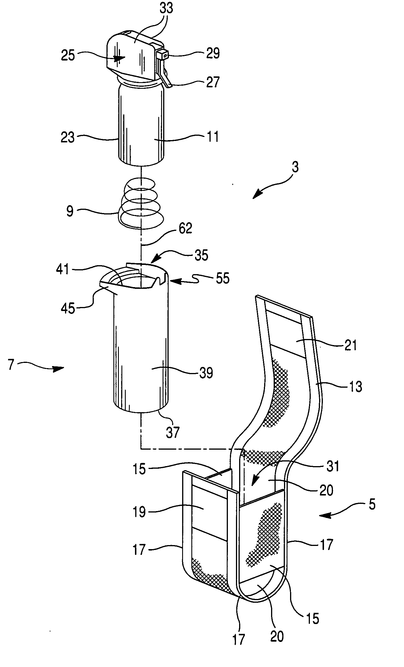
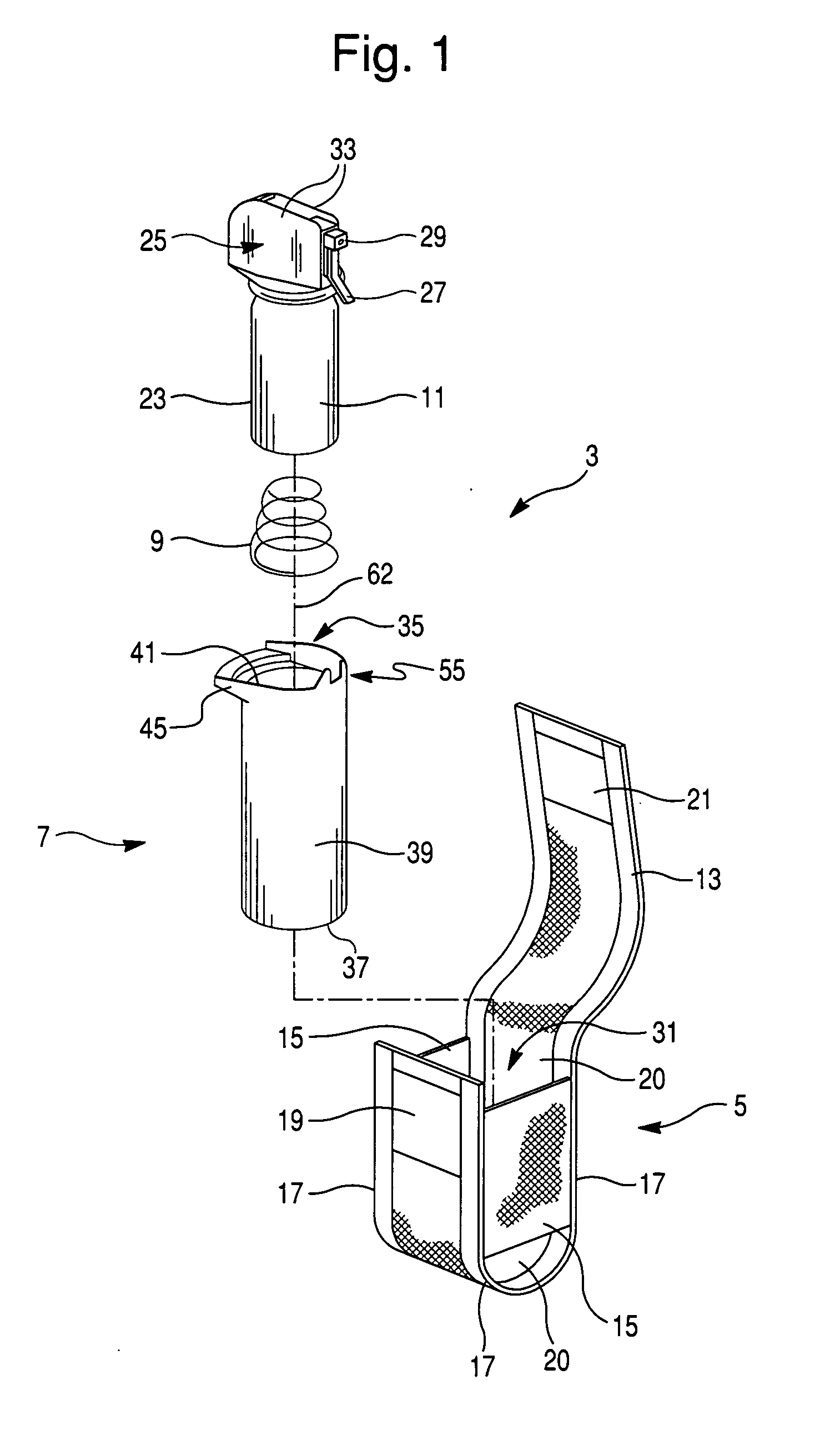
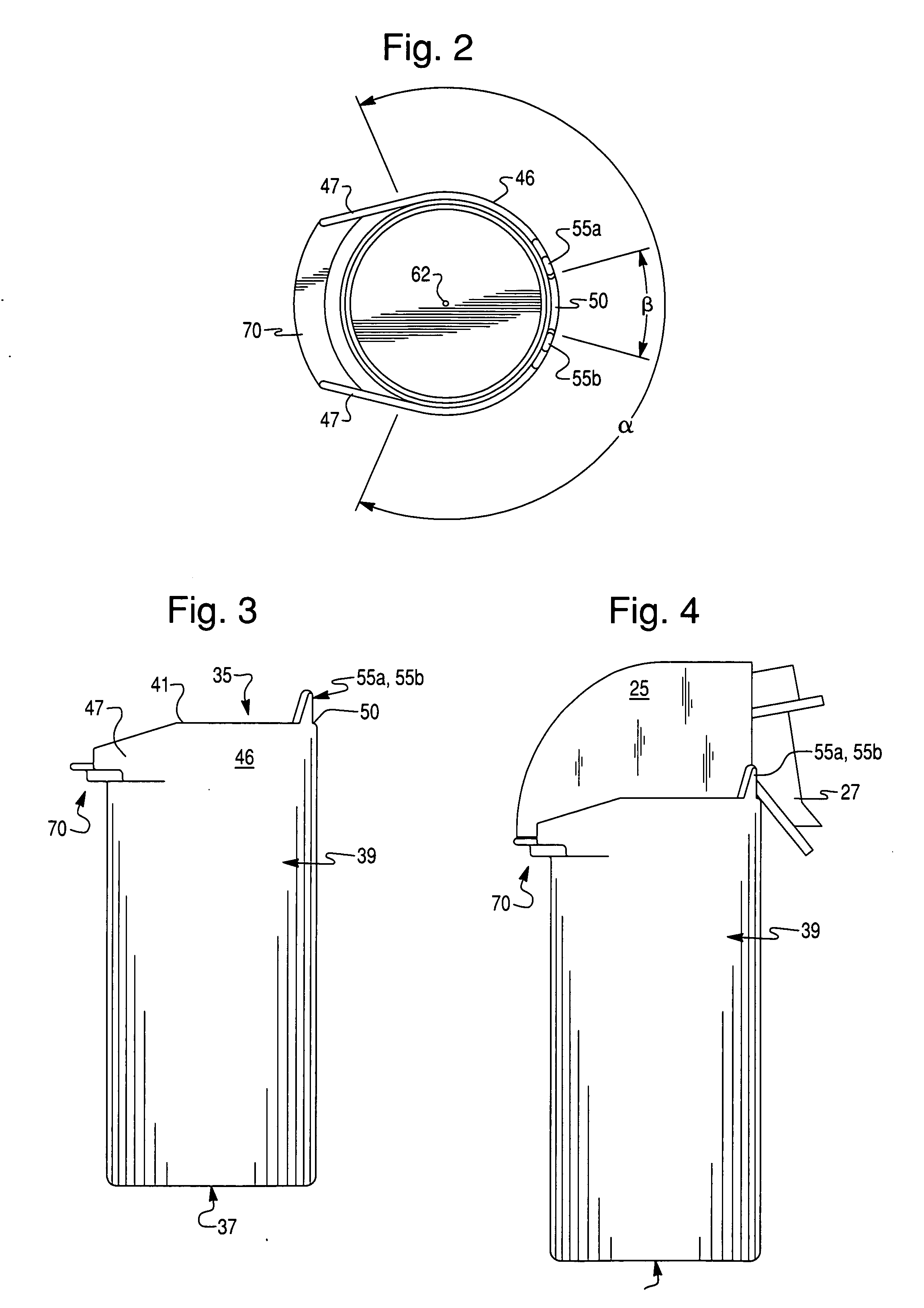
[0019]FIG. 1 is an exploded view of spray container storage and retrieval apparatus / system 3 according to an embodiment of this invention. System 3 includes holster 5, sleeve 7, optional spring 9, and spray canister 11. FIG. 2 is a top view of sleeve 7, while FIG. 3 is a side plan view of sleeve 7. FIG. 4 is a side plan view of sleeve 7 with a canister 11 disposed therein in a position that the canister may assume when the flap of the holster was in a closed position covering the sleeve / canister.

[0020]Referring to FIG. 1, holster 5 includes flexible flap 13, first and second approximately parallel side walls 15, and approximately U-shaped bottom portion 17 which is adapted to receive sleeve 7 therein. Side walls 15 extend between and connect opposing upstanding walls of U-shaped portion 17 of holster 5. Hook and loop (e.g. Velcro®) male...


PUM


Abstract

A spray container storage and retrieval system including a holster for receiving a sleeve therein. The sleeve is designed so as to provide an efficient vertically-oriented channel guard for protecting against accidental discharge of spray containers receivable within the sleeve. In certain embodiments, an optional spring may be provided in a lower portion of the sleeve in order to bias the spray container upwardly therefrom when the holster is opened.

Description

FIELD OF THE INVENTION[0001]This invention relates to an apparatus for enabling an individual to carry a spray container. More particularly, this invention relates to a system and method for carrying a container of spray, such as a self-defense pepper spray or make which enables easy and safe access thereof.DESCRIPTION OF RELATED ART[0002]Systems for carrying spray containers are old and well known in the art. For example, see U.S. Pat. No. 6,145,654; U.S. Pat. No. 5,392,975; and U.S. Pat. No. 5,477,999, the disclosures of which are hereby incorporated herein by reference.[0003]The system of U.S. Pat. No. 5,392,975 includes a holster which receives a sleeve therein. The sleeve is elongated and includes a flange extending laterally outward from its upper end to aid in the formation of a trigger guard. Unfortunately, the upper end flange / trigger guard of the '975 patent is undesirable for a number of reasons. For example, the trigger guard is sometimes ineffective in that once the spr...

Claims


Application Information

Patent Timeline
17 Apr 2008
Publication
US20080087695A1
IPC
B65D83/00; B65D25/04
CPC
A45D2200/057; A45F5/02; A45F5/021; F41H9/10; A45F2200/0591; F41C33/02; A45F2200/0566
Inventors
FROELICH, DAVID T.