Permeable Member, And Permeable Casing And Electrical Component Using The Same

a technology of permeable parts and permeable parts, which is applied in the direction of electrical apparatus casings/cabinets/drawers, lighting and heating apparatus, and separation processes, etc., can solve the problems of affecting the packaging of the casing, the size of the permeable member becomes large, and the difficulty of ensuring the sealing property between the casing and the casing

Active Publication Date: 2008-04-24
NITTO DENKO CORP
View PDF19 Cites 10 Cited by
  • Summary
  • Abstract
  • Description
  • Claims
  • Application Information

AI Technical Summary

Benefits of technology

The present invention provides a permeable member with a support that includes two or more resin materials with different elastic moduli. This results in both a strong pullout strength and good sealing properties.

Problems solved by technology

The technical problem addressed in this patent is to provide a permeable member that can be attached to electrical components and casings of electronic devices, while maintaining both pullout strength and sealing property. This is achieved by using a support with a nonconventional constitution, which allows for a larger elastic modulus without compromising the sealing property between the casing and the permeable member.

Method used


Image

  • Permeable Member, And Permeable Casing And Electrical Component Using The Same
  • Permeable Member, And Permeable Casing And Electrical Component Using The Same
  • Permeable Member, And Permeable Casing And Electrical Component Using The Same

Examples


example

[0069] Hereinafter, the present invention is described in more detail with reference to Examples. The present invention is not limited to the following Examples.

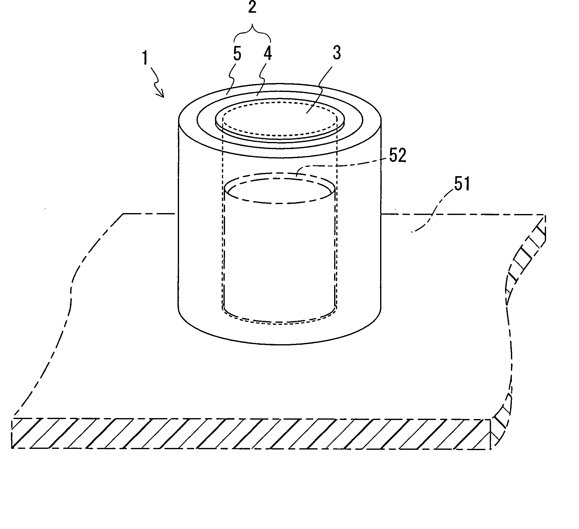
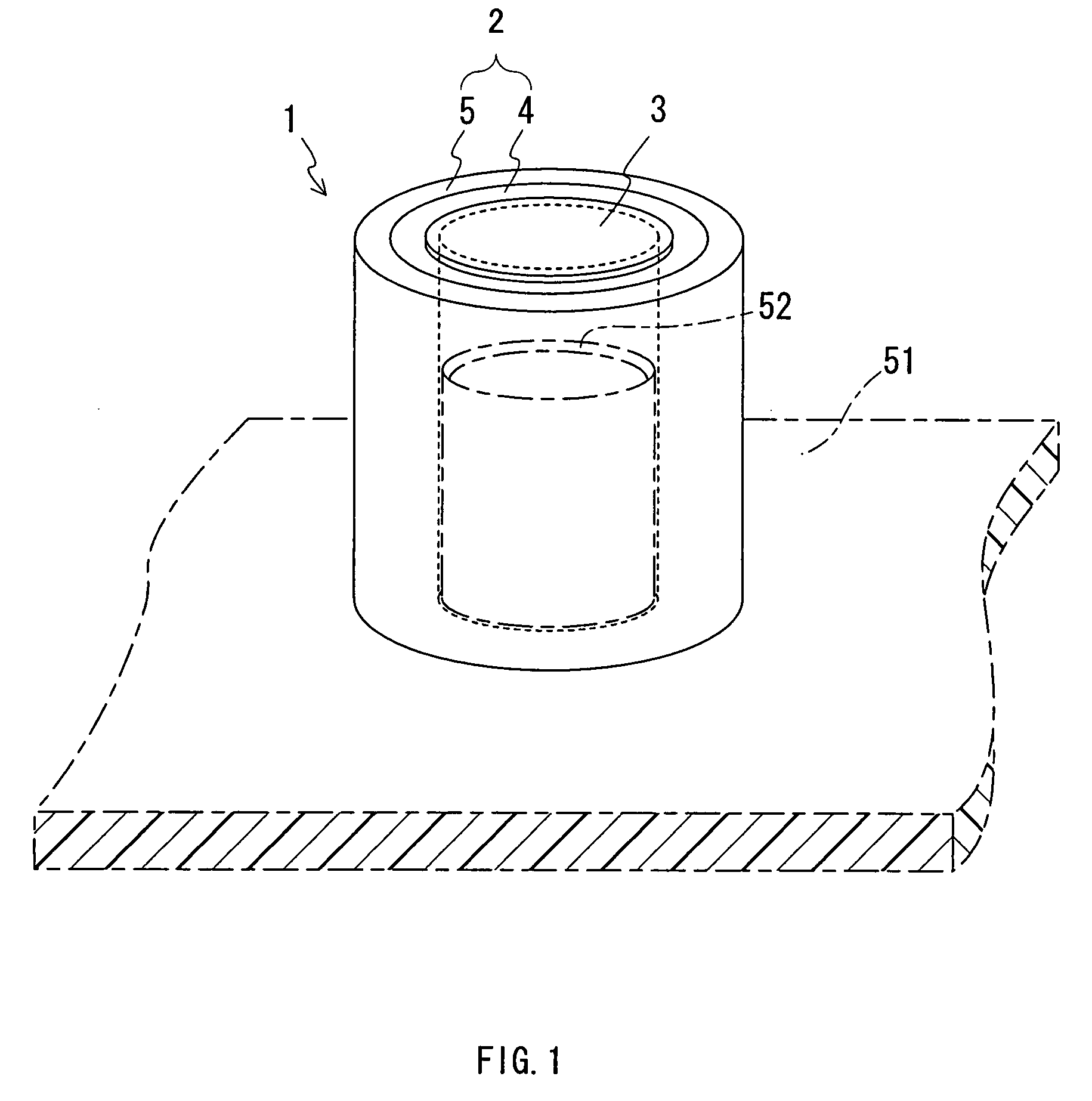
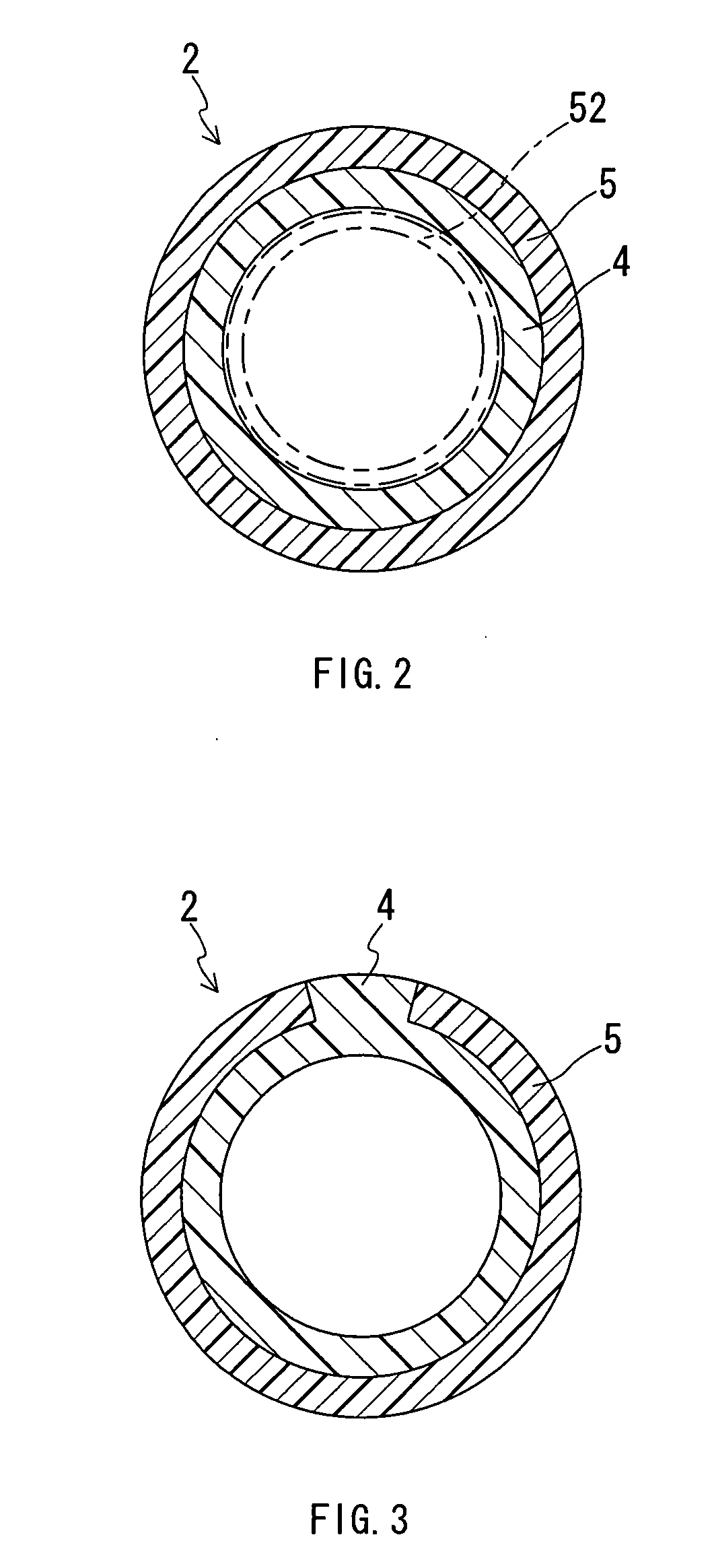
[0070] In these Examples, cylindrical supports shown in FIG. 2 were molded, and the permeable members shown in FIG. 1 and FIG. 13 were produced by fixing and bonding a permeable film to an end face of the molded support. After that, evaluations of the pullout strength and sealing property on the produced permeable members were performed. First, each evaluation method will be described.

[0071]—Evaluation Method of Pullout Strength—

[0072] First, a columnar body (outside diameter: 8 mm) made of polypropylene was inserted into the inside of the support of the produced permeable member so that the insertion depth became 8 mm. After that, the columnar body was pulled out of the support using a tensile testing machine (pullout speed: 50 mm / min) and the maximum value of the force generated during pulling was determined as the pullo...


PUM

PropertyMeasurementUnit
Strengthaaaaaaaaaa
Permeabilityaaaaaaaaaa
Circumferenceaaaaaaaaaa

Abstract

The present invention provides a permeable member which can attain both a pullout strength and following property (sealing property) and provides a permeable casing and an electrical component using the permeable member. The present invention includes a permeable film through which a gas passing an opening passes when the permeable film is fixed to the opening of a casing, and a tubular support that supports the permeable film. The support includes a first resin part that contacts the casing with the support fixed to the opening, and a second resin part composed of a material having a higher elastic modulus than that of a material constituting the first resin part, and the first resin part and the second resin part are laminated at least partly in a transverse section of the support.

Description


Claims


Application Information

Patent Timeline
Owner NITTO DENKO CORP
Why Eureka
Try Eureka