
High-performance textured coating

a textured coating, high-performance technology, applied in the direction of coatings, powdery paints, building components, etc., can solve the problems of poor bonding to concrete, low adhesion strength of coated rebar, and failure of many aggregate materials,

Pending Publication Date: 2022-01-13
SWIMC LLC
View PDF0 Cites 0 Cited by
  • Summary
  • Abstract
  • Description
  • Claims
  • Application Information

AI Technical Summary

Benefits of technology

The textured coating significantly increases the pullout strength of rebar from concrete by up to 30% compared to uncoated or smooth coated rebar, providing improved tensile strength and resistance to seismic forces while reducing the need for additional rebar, thus avoiding concrete congestion and cost increases.

Problems solved by technology

However, many aggregate materials are not known for tensile strength and will fail when subjected to significant tensile load or lateral shaking forces.
However, such coated rebar often suffers from low adhesion strength (i.e. poor bonding to concrete).
This type of rebar can typically withstand substantial tensile loads, but tends to fail when subjected to significant lateral forces, such as the forces that result from an earthquake, for example.
However, in the long term, even pretreated structural insert members tend to disbond from reinforced concrete.
However, increasing the number of structural insert members leads to concrete congestion, where concrete is either poorly compacted or does not penetrate at all.
This leads to poor concrete design, poor concrete placement, and a significant increase in the cost of reinforced concrete without resolving the problem of low adhesion strength.

Method used


Image

  • High-performance textured coating
  • High-performance textured coating
  • High-performance textured coating

Examples


example 1

trength Testing

[0081]Powder compositions were prepared as shown in Table 1 and coated on to test specimens at the indicated film thickness. Pullout strength tests were performed according to ASTM A944-10. Results are shown in Table 1.

TABLE 1Pullout Strength% PulloutFilmPulloutParticlePull-relativethick-persize ofouttonessmmpowderTest SpecimenNmstandardmm(KN)(μm)Uncoated rebar1677————(control)Rebar with corrosion-718.642.90.28256662-70 resistant coating(coated bar)Single layer (textured138182.40.261529130-40 coating)Single layer (textured100660.00.310324560-70 coating)Single layer (textured1831109.20.381480690-100coating)Dual layer (corrosion-2026120.80.3302613690-100resistant first coating +textured secondcoating)

example 2

Surface Roughness on Pullout Strength

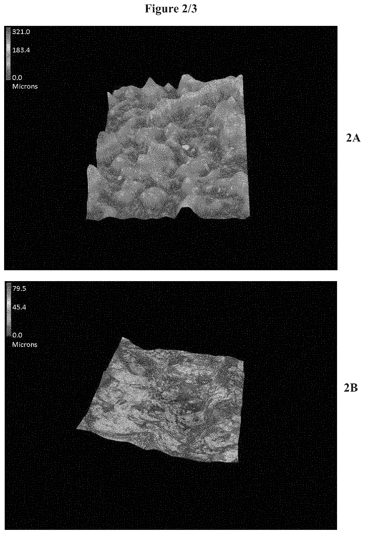
[0082]To determine the effect of surface roughness on pullout strength, metal test bars were coated with formulations #1 to #4 as shown in Table 2. For each test bar, the surface roughness was measured using a light microscope. The surface was imaged as shown in FIG. 2A, which depicts microscope images of a test bar surface with a textured coating applied thereon. FIG. 2B depicts a microscopic image from an uncoated surface.

[0083]For pullout strength testing, each test bar was potted in concrete for pullout testing. A tensile load was applied and each test bar was pulled out of the concrete at a fixed rate. The peak stress for each bar was measured, and results are reported in Table 2. A positive correlation is observed between surface roughness and peak stress.

TABLE 2Surface Roughness and Pullout StrengthSurfacePeakSampleroughnessstressNo.Description(Sz; μm)(KPa)1Bare metal; blasted (control)79.515842Corrosion-resistant coating (smooth)166.91485...

example 3

Surface Roughness on Adhesion to Concrete

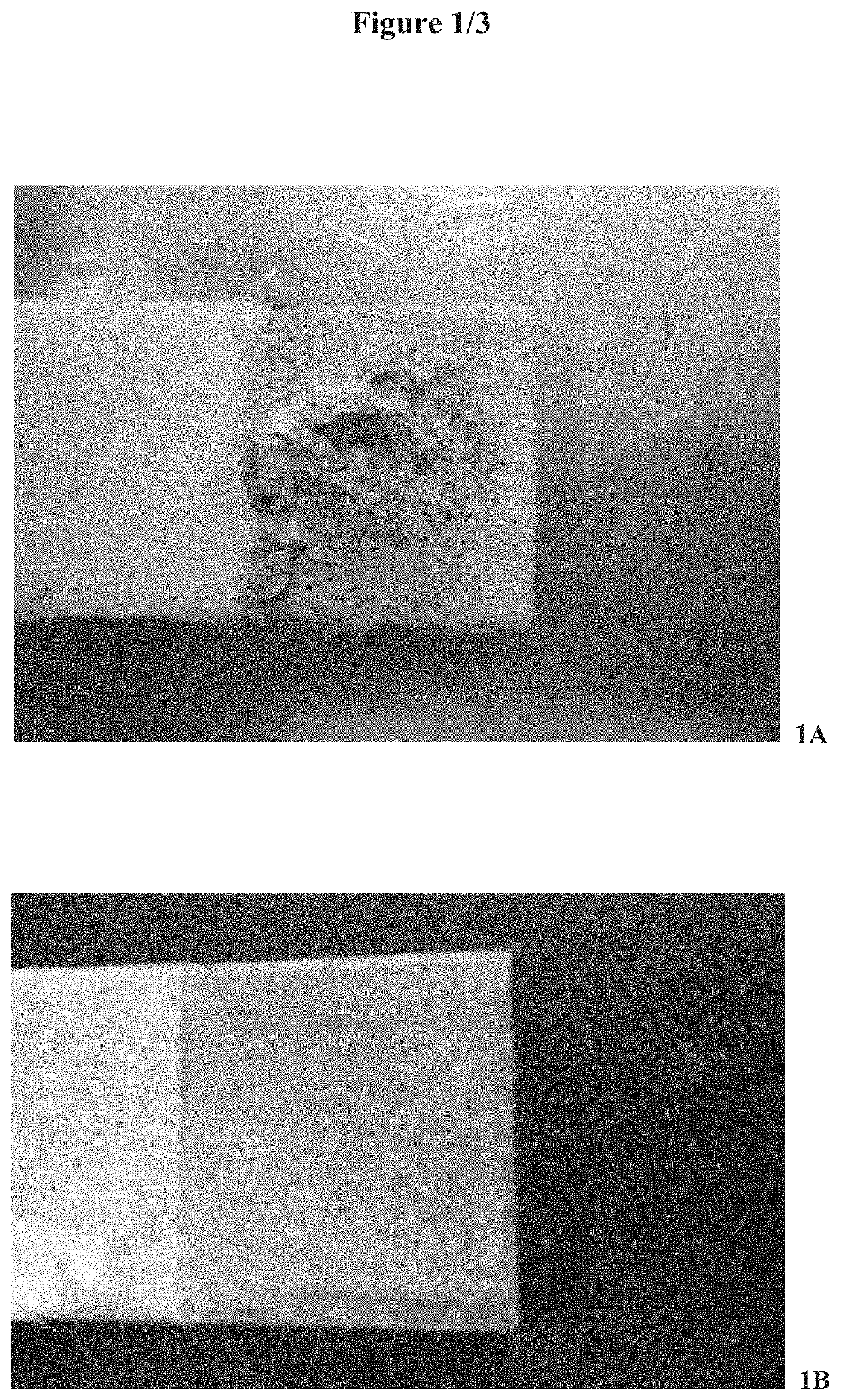
[0084]To demonstrate the effect of surface roughness on the adhesion of a coated metal bar to concrete, powder coating formulations #1 to #4 (as shown in Table 2) were applied to metal test bars and the bars where then potted in concrete. After potting and curing of the concrete, a tensile load was applied and the test bars were pulled out of the concrete at a fixed speed. FIG. 1A depicts a test bar coated with a textured coating and FIG. 1B depicts a test bar with a smooth surface. Concrete remains adhered to the textured coating on the test bar, whereas the test bar with the smooth surface pulls out cleanly from the concrete.


PUM

PropertyMeasurementUnit
temperatureaaaaaaaaaa
median particle sizeaaaaaaaaaa
surface roughnessaaaaaaaaaa

Abstract

A coated article is described, including a substrate with a coating composition applied thereon to provide a coated article with a textured surface. In one aspect, the coated article is a steel rebar used to reinforce concrete. The textured surface provides optimal surface roughness and demonstrates superior pullout strength relative to an uncoated standard.

Description

CROSS REFERENCE TO RELATED APPLICATION(S)[0001]This application is a continuation of U.S. patent application Ser. No. 15 / 789,608, filed 20 Oct. 2017, which is a continuation of International Application No. PCT / US2016 / 030432, filed on 2 May 2016, which claims priority to U.S. Provisional Application Ser. No. 62 / 155,911, filed 1 May 2015, each of which is incorporated herein by reference in its entirety.BACKGROUND OF THE INVENTION[0002]Aggregate materials, such as concrete, for example, are commonly used in various civil and architectural structures and components because these materials are inexpensive and resistant to corrosion and compressive forces. However, many aggregate materials are not known for tensile strength and will fail when subjected to significant tensile load or lateral shaking forces. Therefore, it is common to reinforce aggregate materials by the inclusion or incorporation of rigid structural insert members in the aggregate material.[0003]Reinforced concrete is an...

Claims


Application Information

Patent Timeline
Patent Type & Authority Applications(United States)
IPC IPC(8): B05D5/02C09D163/00C09D5/03B29B7/00E04C5/01E04C2/06C09D5/28C09D5/08C09D7/40B05D7/14B05D3/00E04C5/06E04C5/07
CPCB05D5/02B05D3/0218C09D5/032B29B7/002E04C5/015E04C2/06C09D5/28C09D5/08C09D5/033C09D7/69B05D7/14B05D3/007E04C5/06E04C5/07E04C5/073C08L2207/02C08L2205/14C09D163/00E04C5/01C08L27/18C08K9/06C08K3/34B05D2202/00B05D2401/32B05D2602/00C09D5/00C09D7/65C09D7/61C09D7/63B05D7/24C09D5/024C09D5/03C09D201/00
Inventor SOWINS, JONATHANROGOZINSKI, JEFFREY D.BRONK, JOHN M.KIRKWOOD, KEITH M.POLANCE, ROBERT G.
Owner SWIMC LLC
Learn More