Electrolytic capacitors with a polymeric outer layer

a polymer outer layer and capacitor technology, applied in the field of electrolytic capacitors, can solve the problems of high mechanical stress that may greatly increase the leakage current of the capacitor anode, difficult formation of a thick outer layer by in situ polymerisation, and large number of coating cycles

Active Publication Date: 2006-01-17
HERAEUS PRECIOUS METALS GMBH & CO KG
View PDF5 Cites 480 Cited by
  • Summary
  • Abstract
  • Description
  • Claims
  • Application Information

AI Technical Summary

Benefits of technology

[0191]The electrolytic capacitors according to the invention and the electrolytic capacitors produced according to the invention are eminently suitable as a component in electronic circuits owing to their low leakage current and their low ESR. Digital electronic circuits of the type found, for example, in computers (desktops, laptops, servers), in portable electronic devices, such as mobile telephones and digital cameras, in electronic entertainment equipment, such as in CD / DVD players and computer games consoles, in navigation systems and in telecommunication devices, are preferred.

Problems solved by technology
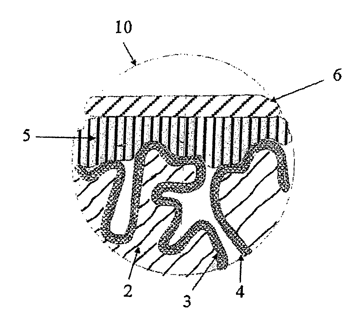
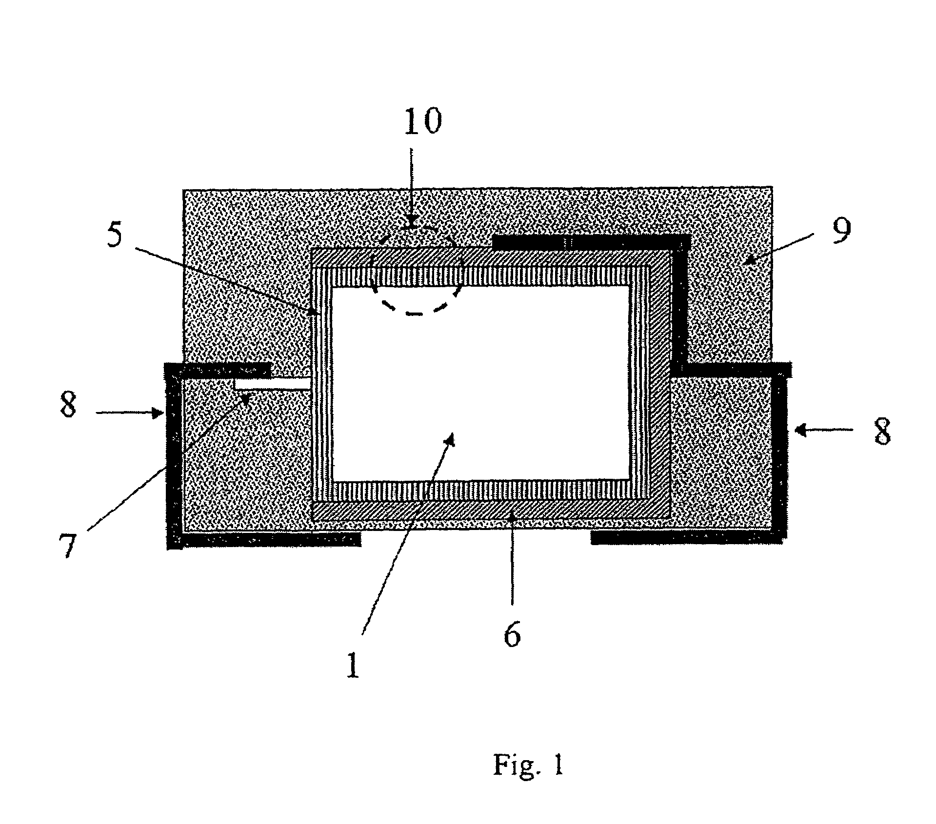
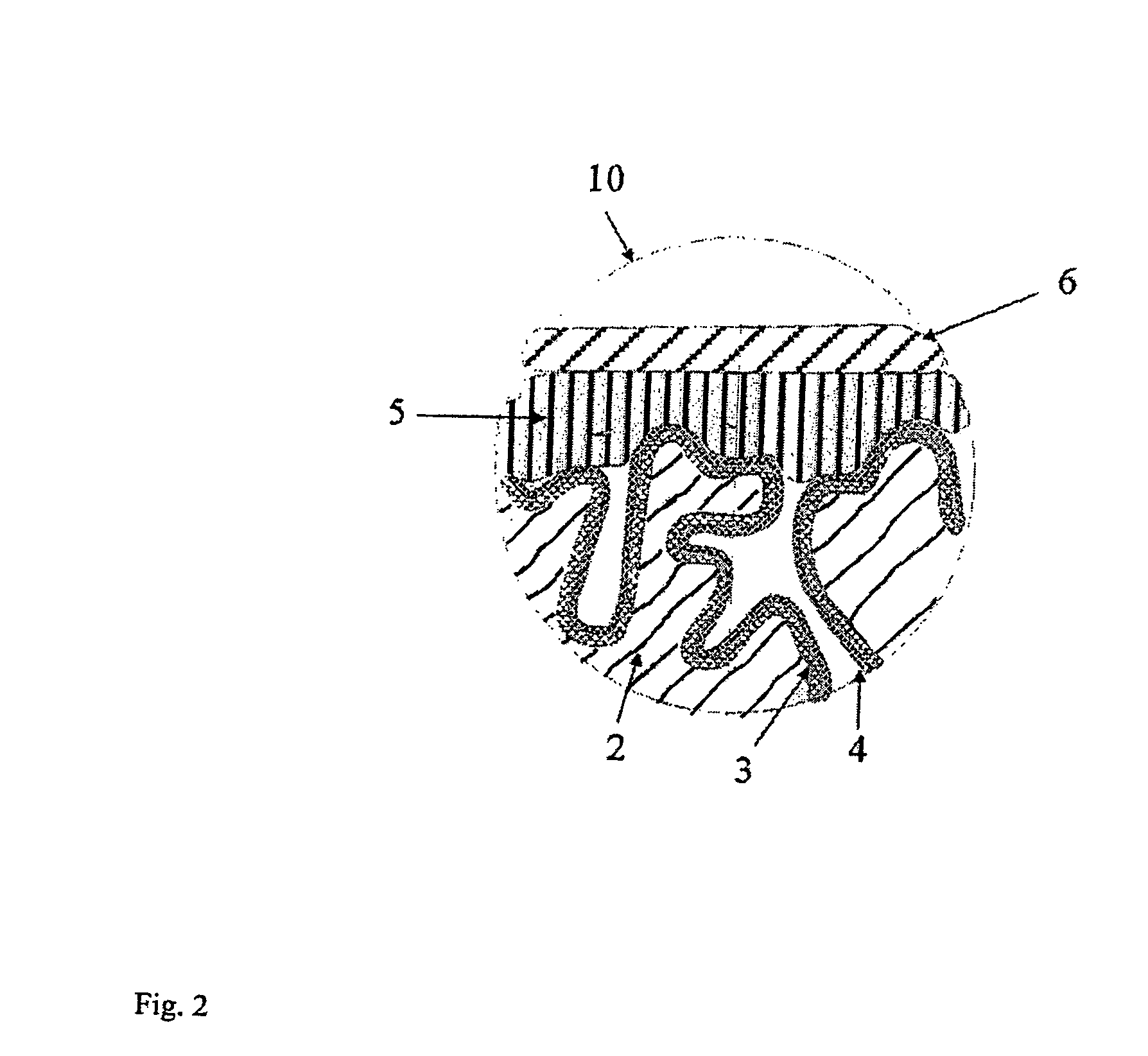
High mechanical stresses that may greatly increase the leakage current of the capacitor anode occur in particular during the production process when encapsulating the capacitor anodes.
The formation of a thick outer layer by in situ polymerisation is very difficult.
Layer formation requires a very large number of coating cycles in this process.
As a result of the large number of coating cycles, the outer layer is coated very unevenly, in particular the edges of the capacitor anode are often inadequately covered.
However, this makes the production process very susceptible to interruptions.
An addition of binder materials for quicker layer build-up is also difficult, as the binder materials hinder the oxidative in situ polymerisation.
This contacting can be very complex in mass production and may damage the oxide layer.
The use of formulations containing the powder of a conductive polymer and binders have excessive electrical resistance owing to the high contact resistance between the individual powder particles, for them to allow production of solid electrolytic capacitors with low ESR.
However, this process has the drawback that the PEDT / PSS complex does not penetrate into porous anode bodies with small pores.
Consequently, modern, highly porous anode materials cannot be used.
However, the drawback of these capacitors is that they have a high ESR of 130 mΩ and higher.

Method used


Image

  • Electrolytic capacitors with a polymeric outer layer
  • Electrolytic capacitors with a polymeric outer layer
  • Electrolytic capacitors with a polymeric outer layer

Examples


example 1

Production of Capacitors According to the Invention

1. Production of Oxidised Electrode Bodies

[0192]Tantalum powder with a specific capacitance of 50,000 μFV / g was compacted into pellets and sintered to form a porous electrode body with dimensions of 4.2 mm*3 mm*1.6 mm. The pellets (anode pellets) were anodised in a phosphoric acid electrolyte to 30 V.

2. Chemical In Situ Coating of the Anode Pellets

[0193]A solution, comprising one part by weight 3,4-ethylenedioxythiophene (BAYTRON® M, H. C. Starck GmbH and 20 parts by weight of a 40% ethanolic solution of iron(III)-p-toluenesulphonate (BAYTRON® C-E, H. C. Starck GmbH) was produced.

[0194]The solution was used to impregnate 9 anode pellets. The anode pellets were steeped in this solution and then dried for 30 min at ambient temperature (20° C.). They were then heat treated for 15 min at 50° C. and 15 min at 150° C. in a drying oven. The pellets were then washed for 30 min in water. The anode pellets were reformed for 30 min in a 0.25% ...

example 2

Production of Capacitors According to the Invention

[0201]Tantalum powder with a specific capacitance of 50,000 μFV / g was compacted into pellets and sintered to form a porous electrode body with dimensions of 4.2 mm*3 mm*0.8 mm. The pellets (anode pellets) were anodised in a phosphoric acid electrolyte to 30 V.

[0202]The chemical in situ coating and application of the polymeric outer layer were carried out according to Example 1 (step 2 and 3).

[0203]After application of the polymeric outer layer, the anode pellets were observed under a light microscope: the entire external surface was covered with a dense polymer film. The edges exhibited a continuous polymer film coating.

[0204]FIG. 3 shows a light microscopic photograph of a fractured surface of the capacitor according to the invention. An approximately 5 to 10 μm thick polymer outer layer that also very effectively surrounds the edge of the capacitor pellet may clearly be seen.

[0205]Two of the anode pellets were coated with a graphi...

example 3

Resistance of Capacitors According to the Invention to Mechanical Stresses

[0217]The capacitors according to the invention from Example 1 were contacted on the silver layer by means of a metal spring bolt (spring force 3 N, round bearing surface with diameter of 1.5 mm, bearing pressure approximately 170 N / cm2 or 17 bar) for measuring leakage current.

[0218]The leakage current at 10 V increased with this high mechanical stress from, on average, 5 μA to 144 μA.

[0219]The capacitors not according to the invention from Example 4A with an outer layer polymerised in situ were subjected to the same stress test. A 10 V voltage could not be applied to the 6 capacitors with a leakage current of 1 μA from Example 4A without electrical short-circuits being produced. Even at 0.5 V the capacitors exhibited an average leakage current of almost 2,000 μA.

[0220]This example shows that the capacitors according to the invention have high stability to mechanical stresses.


PUM

PropertyMeasurementUnit
equivalent series resistanceaaaaaaaaaa
thicknessaaaaaaaaaa
temperatureaaaaaaaaaa

Abstract

Electrolytic capacitors having low equivalent series resistance and low leakage current are described. The electrolytic capacitors include a solid electrolyte layer of a conductive material in particular a conductive polymer, and an outer layer that includes binders, polymeric anions and conductive polymers (e.g., polythiophenes). Also described is a method of preparing electrolytic capacitors that involves forming the conductive polymer of the solid electrolyte layer in situ by means of chemical oxidative polymerization or electrochemical polymerization. Electronic circuits that include the electrolytic capacitors are also described.

Description

CROSS REFERENCE TO RELATED PATENT APPLICATION[0001]The present patent application claims the right of priority under 35 U.S.C. §119 (a)-(d) of German Patent Application No. 103 49 112.0, filed Oct. 17, 2003.FIELD OF THE INVENTION[0002]The invention relates to electrolytic capacitors with low equivalent series resistance and low leakage current consisting of a solid electrolyte made of conductive polymers and an outer layer containing conductive polymers and polymeric anions, to the production thereof and to the use of such electrolytic capacitors.BACKGROUND OF THE INVENTION[0003]A solid electrolytic capacitor generally consists of a porous metal electrode, an oxide layer located on the metal surface, an electrically conductive solid introduced into the porous structure, an outer electrode, such as a silver layer, and further electric contacts and encapsulation.[0004]Examples of solid electrolytic capacitors are tantalum, aluminium, niobium and niobium oxide capacitors with charge tr...

Claims


Application Information

Patent Timeline
Patent Type & Authority Patents(United States)
IPC IPC(8): H01G9/00H01G9/028H01G9/025H01G9/032H01G9/052H01G9/10H01G9/14H01G9/15
CPCH01G9/10H01G9/15H01G11/48H01G11/56Y10T29/417Y02E60/13H01G9/025
Inventor MERKER, UDOWUSSOW, KLAUSJONAS, FRIEDRICH
Owner HERAEUS PRECIOUS METALS GMBH & CO KG
Why Eureka
Try Eureka