Compressor Control System for a Portable Ventilator

a control system and portable technology, applied in the direction of electronic commutators, process and machine control, instruments, etc., can solve the problems of simple bldc motor controllers, low precision of speed control required in portable ventilator systems, and low accuracy of speed control loops, so as to achieve cost-effective and small packages

Active Publication Date: 2008-04-24
VYAIRE MEDICAL 203 INC
View PDF99 Cites 27 Cited by
  • Summary
  • Abstract
  • Description
  • Claims
  • Application Information

AI Technical Summary

Benefits of technology

[0044] In one embodiment of the invention, analog sensors are located within a BLDC motor assembly to provide continuous signals based on the magnetic flux sensed from a magnet attached to the rotor of the motor. Unlike the prior art, sensor signals may be sampled at a sample rate that is independent of the angular speed of the rotor. Speed and position accuracy can therefore be maintained across the full range of rotor speeds.

Problems solved by technology

However, simple BLDC motor controllers (e.g., controllers that rely solely on commutation states for motor control) do not provide the type of precision speed control required in portable ventilator systems.
Speed detection based on sparse commutation state information would have a strong negative impact on the transient response of the speed control loop, especially at low speeds.
For speed control, however, such coarse position information is problematic.
However, as the rotor speed decreases, the commutation position samples become sparser in time, increasing the amount of time required to compute an accurate speed value.
As a result, the speed computations from commutation information provide a transient response that is too slow for portable ventilator applications.
A disadvantage of optical encoders and other speed transducers is that the extra hardware of the encoder takes up space in the housing of the device and increases the overall weight of the device.
Further, optical encoders are expensive.
For larger devices, the increased size, weight and cost may not be important factors in the device design.
Thus, the additional size, weight and cost of separate speed transducers make them undesirable as solutions for speed control in a portable ventilator.
These shortcomings of prior art BLDC control systems hinder the use of separate speed transducers with BLDC motors in mechanical ventilator applications.

Method used


Image

  • Compressor Control System for a Portable Ventilator
  • Compressor Control System for a Portable Ventilator
  • Compressor Control System for a Portable Ventilator

Examples


Embodiment Construction

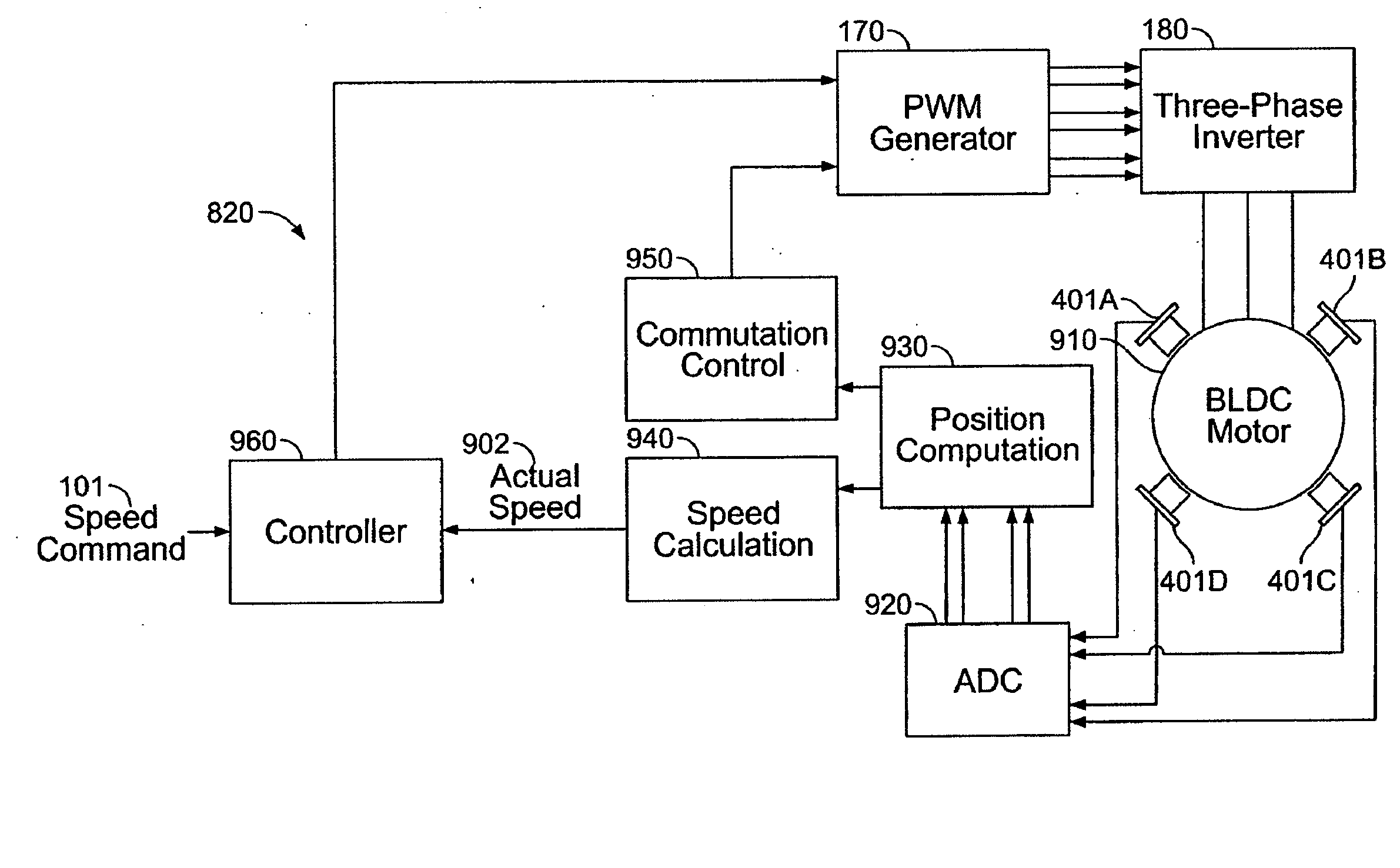
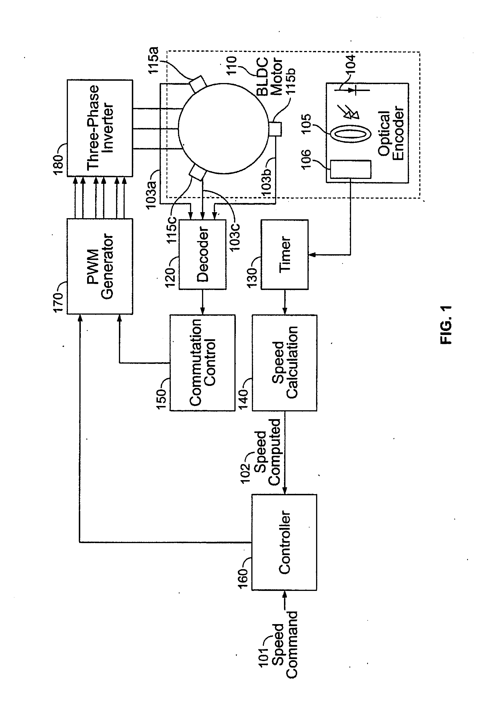
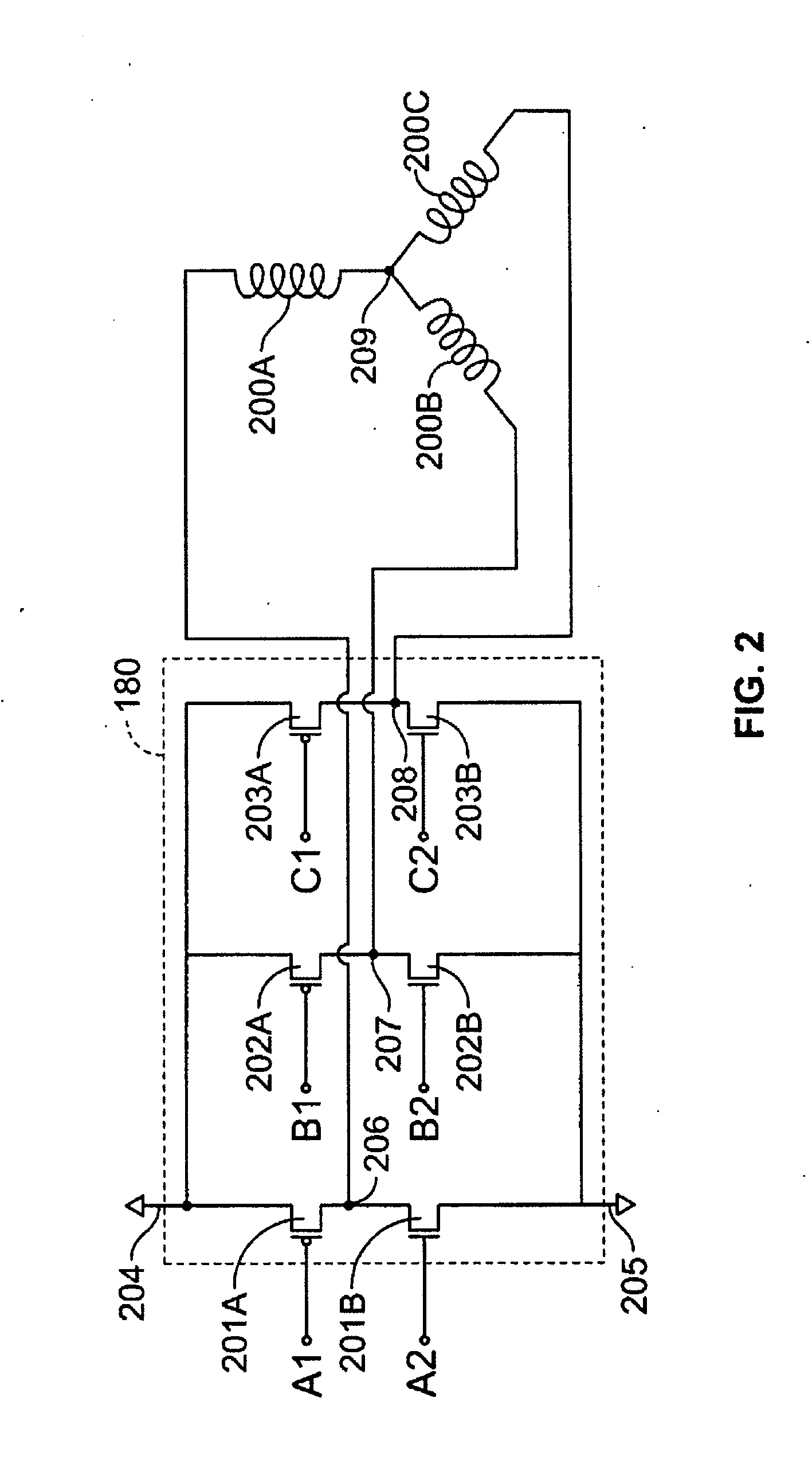
[0046] The invention provides a control system for a brushless DC motor that can be used to drive a compressor in a portable mechanical ventilator. In the following description, numerous specific details are set forth to provide a more thorough description of embodiments of the invention. It will be apparent, however, to one skilled in the art, that the invention may be practiced without these specific details. In other instances, well known features have not been described in detail so as not to obscure the invention.

[0047] Mechanical ventilators are normally bulky machines used mostly in hospitals to assist patients who cannot breathe on their own. Recent advances in technology have resulted in a generation of portable generators that can be used outside the hospital. The current trend is to reduce the size and power consumption of mechanical ventilators while providing the full capability of full size hospital ventilator units.

[0048] Mechanical ventilators create positive intra...


PUM


Abstract

A method and apparatus for controlling a brushless DC (BLDC) motor over a wide range of angular speeds is presented. Analog magnetic sensors provide continuous signal measurements related to the rotor angular position at a sample rate independent of rotor angular speed. In one embodiment, analog signal measurements are subsequently processed using an arctangent function to obtain the rotor angular position. The arctangent may be computed using arithmetic computation, a small angle approximation, a polynomial evaluation approach, a table lookup approach, or a combination of various methods. In one embodiment, the BLDC rotor is used to drive a Roots blower used as a compressor in a portable mechanical ventilator system.

Description

CROSS-REFERENCE TO RELATED APPLICATIONS [0001] This application claims priority to and is a continuation of U.S. patent application Ser. No. 10 / 847,693, titled “Compressor Control System for a Portable Ventilator,” filed on May 18, 2004, which claims priority to U.S. Provisional Application No. 60 / 492,421, to Douglas F. DeVries, titled “Portable Ventilator,” filed on Aug. 4, 2003, the disclosures of which are hereby incorporated by reference in their entirety.BACKGROUND OF THE INVENTION [0002] 1. Field of the Invention [0003] This invention relates to control systems for electric motors, more particularly to a control system for an electric motor used to drive a compressor in a portable ventilator. [0004] 2. Background Art [0005] For a variety of reasons, there are instances when individuals (patients) with acute and chronic respiratory distress cannot ventilate themselves (i.e. breathe). In those circumstances, such patients require breathing assistance to stay alive. One solution ...

Claims


Application Information

Patent Timeline
Patent Type & Authority Applications(United States)
IPC IPC(8): G05D7/06A61M16/00H02P7/285A62B7/00
CPCA61M11/00A61M16/206A61M16/0057A61M16/0066A61M16/12A61M2016/0021A61M2016/0036A61M2016/1025A61M2202/0208A61M2205/16A61M2205/3317A61M2205/3365A61M2205/3368A61M2205/3553A61M2205/3569A61M2205/3584A61M2205/42A61M2205/505A61M2205/52A61M2205/581A61M2205/583A61M2205/70A61M2205/8206A61M2205/8237A61M2205/8262A61M2209/086A61M2230/205A61M2230/432A61M2230/435H02P6/165A61M16/0063A61M16/0069A61M16/205A61M16/0051A61M16/026A61M16/107A61M16/202A61M16/209H02P6/17
Inventor BOYLE, DAVIDHOLMES, MICHAELWILLIAMS, MALCOLM
Owner VYAIRE MEDICAL 203 INC
Why Eureka
Try Eureka