Air circuit system for portable respirator

A portable and ventilator technology, applied in the direction of respirators, etc., can solve the problems of complex composition of the gas circuit system, complex parameter settings, and large space occupied by the whole machine, so as to achieve simple composition of the gas circuit system, reduce setting time, and be convenient to carry Effect

Inactive Publication Date: 2014-12-03
SUZHOU PINNOVATION MEDICAL TECH CO LTD
View PDF5 Cites 0 Cited by
  • Summary
  • Abstract
  • Description
  • Claims
  • Application Information

AI Technical Summary

Problems solved by technology

[0002] Traditional ventilator, air circuit structure such as figure 1 As shown, it consists of a main gas circuit (oxygen circuit) and a branch gas circuit (air circuit). Oxygen flows through the filter F1 to the pressure reducing valve REG1, then to the needle valve, Venturi, and finally to the patient breathing valve. The main gas circuit There is also a safety valve SV, an oxygen concentration detection valve OS and a free breathing valve EV1, a branch routing filter F2, a one-way valve DV1, and a flow regulating valve NV2. During the working process of the ventilator, the breathing frequency and minute ventilation are not adjusted. Relevance, separate control is required, and parameter settings are complicated; the air circuit components of the whole machine include filters, pressure sensors, pressure reducing valves, solenoid valves, needle valves, Venturi, one-way valves, flow regulating valves, safety valves, oxygen concentration Composed of a detection valve and a free breathing valve, the air system is complex, the machine is large in size and inconvenient to carry, and is not suitable for use in emergency transfer occasions
This kind of ventilator that can solve the problem of complicated setting of ventilator parameters and takes up a lot of space has not yet appeared or related technologies have not yet been made public.

Method used


Image

  • Air circuit system for portable respirator
  • Air circuit system for portable respirator
  • Air circuit system for portable respirator

Examples


Embodiment Construction

[0021] At first, the portable ventilator of specific embodiment of the present invention is described:

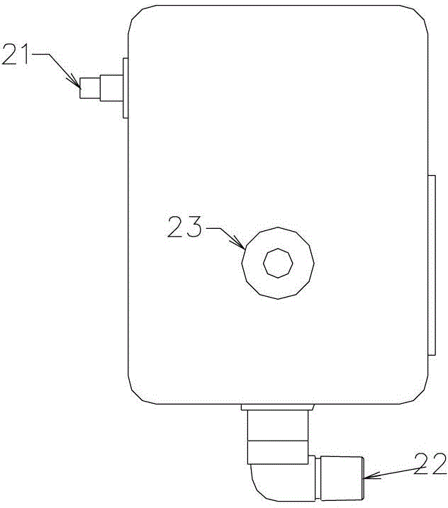
[0022] The portable ventilator has an external structure such as figure 2 As shown, only one air source input port 21 is connected to the oxygen cylinder, and the ventilator output port 22 is connected to the user through the patient breathing valve. The portable ventilator is provided with a linkage adjustment knob 23 for linkage control of minute ventilation volume and respiratory rate.

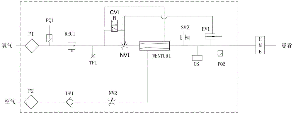
[0023] Second, the portable ventilator gas circuit system of the specific embodiment of the present invention is described:

[0024] The gas system, the structure is as follows image 3 As shown, it includes the gas circuit communication pipeline connected between the output port 22 of the ventilator and the only gas source input port 21 and the pressure reducing valve REG1 and the flow regulating valve NV connected from the inlet to the outlet gas circuit; the system also includes T...


PUM


Abstract

The invention relates to an air circuit system for a portable respirator. The air circuit system comprises an air circuit communicating pipeline, a pressure reducing valve (REG1) and a flow adjusting valve (NV), wherein the air circuit communicating pipeline is connected between a respirator output end (22) and a unique air source input end (21); the REG1 and the NV are arranged on the air circuit communicating pipeline and are serially communicated by an input-output air circuit; the air circuit system further comprises a two-position and three-way control valve (SV1) and a free respiration valve (EV1); the air output end (32) of the SV1 is divided into two paths which are in respectively air circuit communication with a control end of the EV1 and a control end of the NV; a first air inlet end (31) of the SV1 is in bypass air circuit communication with an air circuit communicating pipeline between the REG1 and the NV; a second air input end (33) of the SV1 is in bypass air circuit communication with an air circuit communicating pipeline between the NV and the output end of the respirator; and the EV1 is in bypass air circuit communication with an air circuit communicating pipeline between the NV and the output end of the respirator. The air circuit system further comprises a linking adjustment device (GS1) for linking adjustment of the NV and adjusting the SV1 to conduct the switch frequency through a variable electronic element.

Description

technical field [0001] The invention relates to medical equipment, in particular to a portable ventilator gas circuit system. Background technique [0002] Traditional ventilator, air circuit structure such as figure 1 As shown, it consists of a main gas circuit (oxygen circuit) and a branch gas circuit (air circuit). Oxygen flows through the filter F1 to the pressure reducing valve REG1, then to the needle valve, Venturi, and finally to the patient breathing valve. The main gas circuit There is also a safety valve SV, an oxygen concentration detection valve OS and a free breathing valve EV1, a branch routing filter F2, a one-way valve DV1, and a flow regulating valve NV2. During the working process of the ventilator, the breathing frequency and minute ventilation are not adjusted. Relevance, separate control is required, and parameter settings are complicated; the air circuit components of the whole machine include filters, pressure sensors, pressure reducing valves, solen...

Claims


Application Information

Patent Timeline
Patent Type & Authority Patents(China)
IPC IPC(8): A61M16/00
Inventor 袁波盛倩倩于邦仲
Owner SUZHOU PINNOVATION MEDICAL TECH CO LTD
Why Eureka
Try Eureka