Preconditioner having independently driven high-speed mixer shafts

Active Publication Date: 2008-04-24
WENGER MFG LLC
View PDF18 Cites 30 Cited by
  • Summary
  • Abstract
  • Description
  • Claims
  • Application Information

AI Technical Summary

Benefits of technology

[0012]In alternate forms, the preconditioner may be of the type having juxtaposed, intercommunicated chambers of the same cross sectional area, each equipped with a

Problems solved by technology

As such, increasing the rotational speed of the beaters of conventional preconditioners in an attempt to increase agitation within the vessel causes the materials to pass through the vessel at a greater speed which correspondingly reduces the residence time of the materials within the vessel to values that may be unacceptable.
On the other hand, reducing the rotational speed of the beaters to increase residence time within the vessel adversely affects the mixing characteristics of the vessel to the point where proper blending of the materials with water is not achieved.
Increasing the overall length of the vessel is not desirable because of mechanical problems associated with the mixing shafts.
Moreover, the structural nature of conventional preconditioning apparatus does not lend i

Method used


Image

  • Preconditioner having independently driven high-speed mixer shafts
  • Preconditioner having independently driven high-speed mixer shafts
  • Preconditioner having independently driven high-speed mixer shafts

Examples


Embodiment Construction

Embodiment of FIGS. 1-5

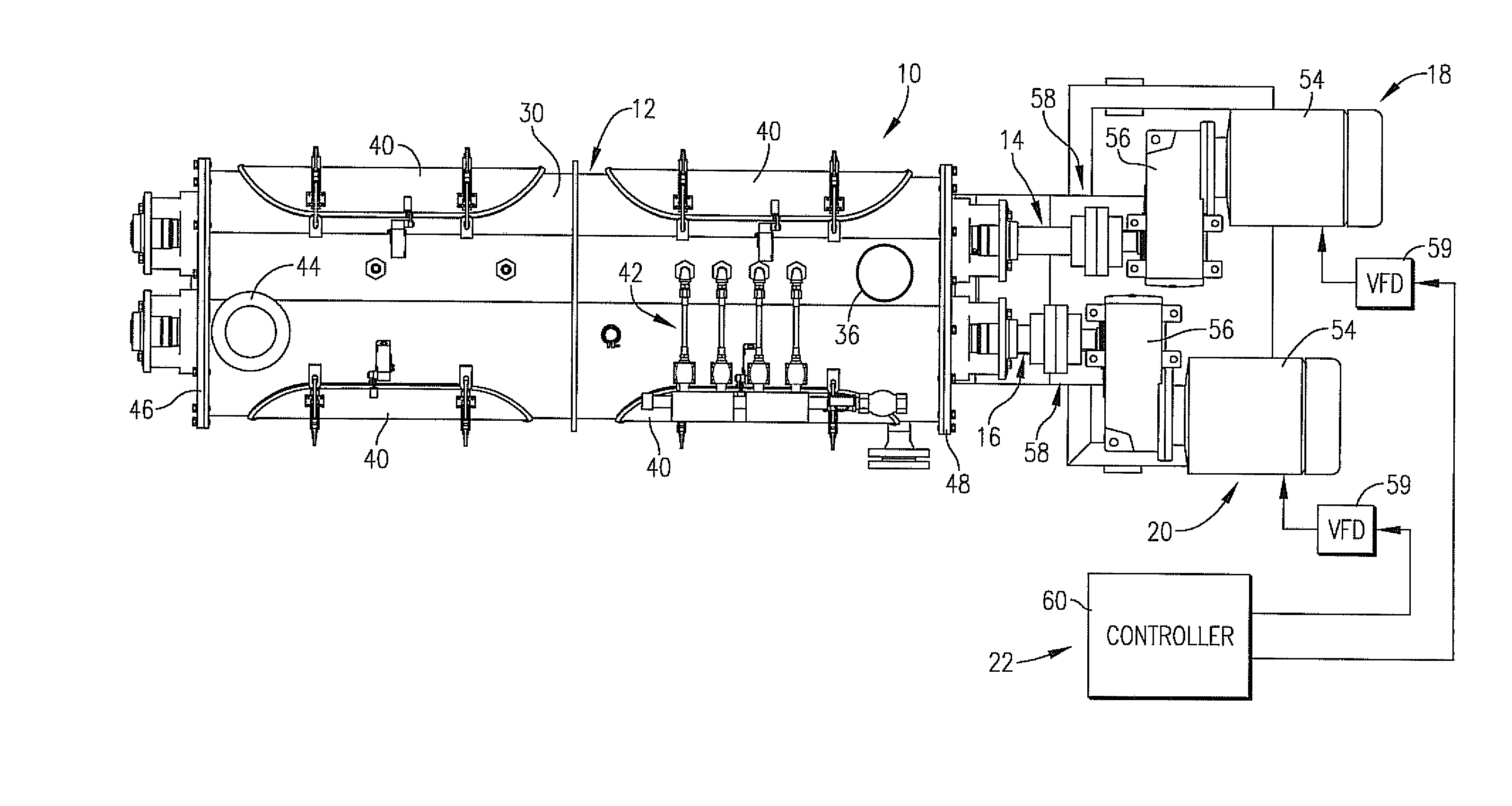
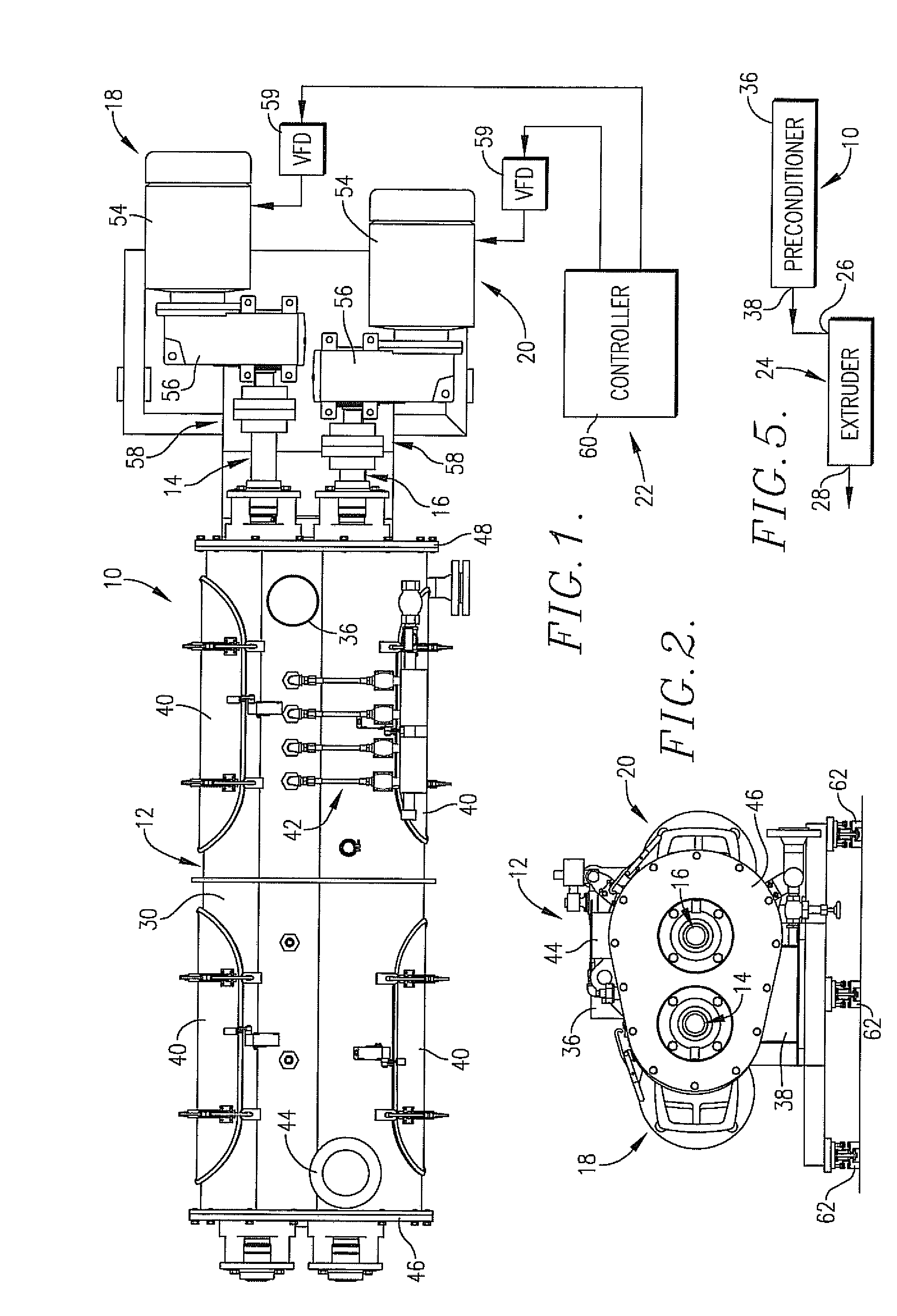
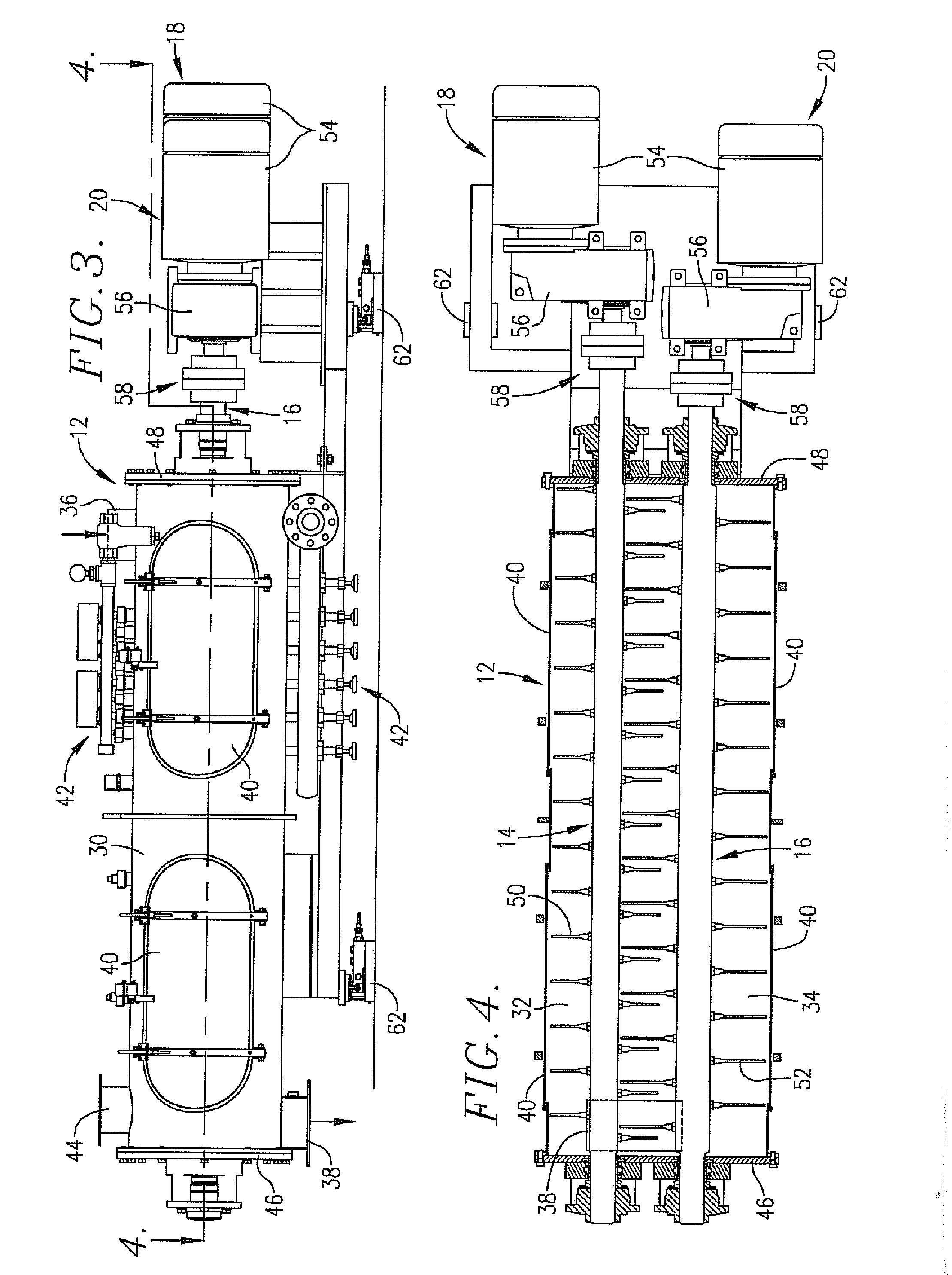
[0021]Turning now to the drawings, an improved preconditioner 10 is depicted in FIGS. 1-4. Broadly, the preconditioner 10 includes an elongated mixing vessel 12 with a pair of parallel, elongated, axially-extending mixing shafts 14 and 16 within and extending along the length thereof. The shafts 14, 16 are operably coupled with individual variable drive devices 18 and 20, the latter in turn connected with digital controller 22. The preconditioner 10 is adapted for use with a downstream processing device such as an extruder or pellet mill. As depicted in FIG. 5, the preconditioner 10 is coupled with an extruder 24 (which may be of the single or twin screw variety) having an inlet 26 and a restricted orifice die outlet 28, as well as an internal, axially rotatable screw.

[0022]In more detail, the vessel 12 has an elongated, transversely arcuate sidewall 30 presenting a pair of elongated, juxtaposed, intercommunicated chambers 32 and 34, as well as a material inle...


PUM


Abstract

An improved, dual-shaft preconditioner (10, 70) is provided having independent drive mechanism (18, 20, 78, 80) operatively coupled with a corresponding preconditioner shaft (14, 16, 74, 76) and permitting selective rotation of the shafts (14, 16, 74, 76) at rotational speeds and directions independent of each other. The mechanisms (18, 20, 78, 80) are operatively coupled with a digital controller (60) to allow rotational speed and direction control. Preferably, the preconditioner (10, 70) is supported on load cells (62, 100) also coupled with controller (60) to permit on-the-go changes in material retention time within the preconditioner (10, 70). The preconditioner (10, 70) is particularly useful for the preconditioning and partial gelatinization of starch-bearing feed or food materials.

Description

BACKGROUND OF THE INVENTION[0001]1. Field of the invention[0002]The present invention is broadly concerned with improved, dual mixing shaft preconditioners of the type used upstream of processing devices such as extruders or pellet mills in the production of animal feeds or human foods. More particularly, the invention is concerned with such preconditioners, and processing systems making use thereof, wherein the preconditioners include variable drive mechanisms operably coupled with the mixing shafts and designed to permit selective rotation of the shafts at individual rotational speeds independent of each other.[0003]2. Description of the Prior Art[0004]Preconditioners are widely used in combination with extruders for preparing and blending food materials before further processing and cooking of the same in an extruder. For example, products having a relatively high percentage of flour-like material are often blended with water and treated with steam in a conditioner prior to extru...

Claims


Application Information

Patent Timeline
IPC IPC(8): B01F7/04
CPCB01F7/042B01F7/043B01F15/00194Y10S388/936B01F15/00376Y10S366/601B01F15/00253B01F27/703B01F27/702B01F35/2117B01F35/22142B01F35/2209Y02P70/10
Inventor WENGER, LAVONWENGER, MARCSTRAHM, MICHAEL J.
Owner WENGER MFG LLC
Why Eureka
Try Eureka