

Head/arm subassembly and head stack assembly for media servowriter
- Summary
- Abstract
- Description
- Claims
- Application Information
AI Technical Summary
Benefits of technology
Problems solved by technology
Method used
Image

Examples
Embodiment Construction
[0034] The present invention may be understood more readily by reference to the following detailed description of certain embodiments of the invention. However, it will be understood by those skilled in the relevant art that the present invention may be practiced without these specific details. In other instances, well-known methods, procedures, and components have not been described in detail so as not to obscure the present invention.
[0035] Throughout this application, where publications are referenced, the disclosures of these publications are hereby incorporated by reference, in their entireties, into this application in order to more fully describe the state of art to which this invention pertains.
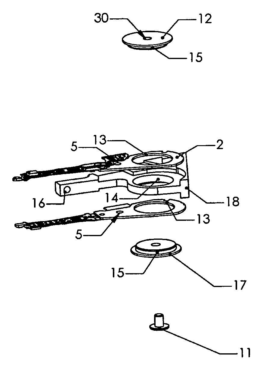
[0036] The present invention is intended to provide a read-write head stack assembly that comprises a plurality of read-write head / arm subassemblies, where the read-write head stack assembly can be employed in a disk drive such as media servowriter for reading from and writing onto ...
PUM
 Abstract
Description
Claims
Application Information