Piston pin puller adaptor tool

Active Publication Date: 2014-05-06
MOTION PRO
View PDF8 Cites 0 Cited by
  • Summary
  • Abstract
  • Description
  • Claims
  • Application Information

AI Technical Summary

Benefits of technology

[0014]An advantage of the present invention is that it is usable on both short skirt pistons and full skirt pistons.
[0015]Another advantage of the present invention is that it is usable on short skirt pistons without risking damage to the rings and ring lands.
[0016]A further advantage of the present invention is one tool includes replaceable sleeves, which are configured for both full skirt and short skirt pistons.
[001

Problems solved by technology

The head of the piston is exposed to repeated bursts from compressed ignited gasoline and air in the cylinder, and therefore become worn with time and periodically require replacement.
Thus, a considerable amount of force may be required to draw the pin and to allow the piston to be removed.
However, when this configuration is used with a short skirt piston, most of th

Method used


Image

  • Piston pin puller adaptor tool
  • Piston pin puller adaptor tool
  • Piston pin puller adaptor tool

Examples


Example

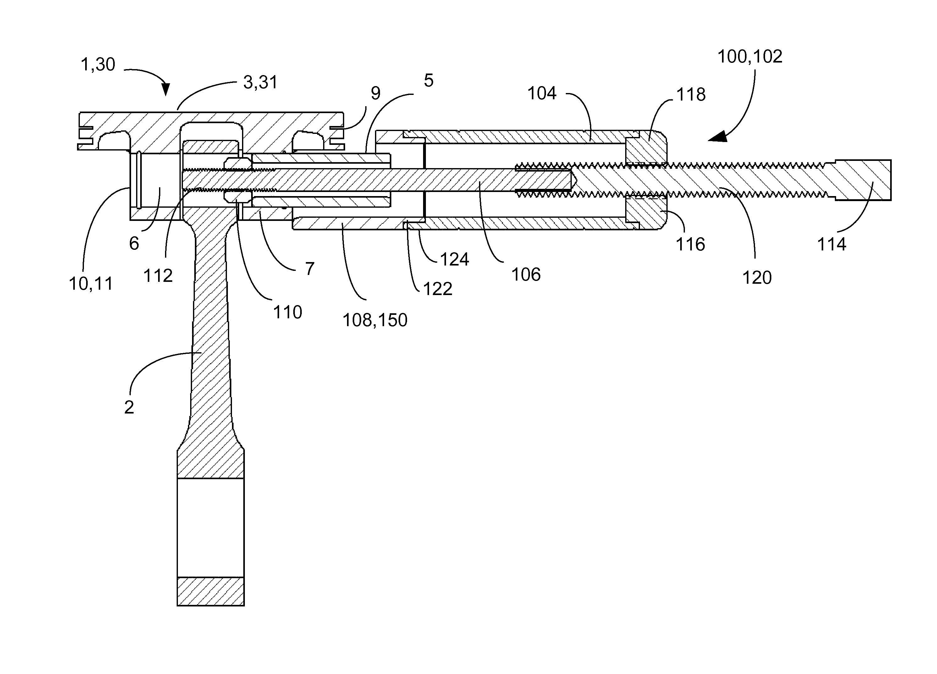
[0031]The present invention is a pin puller adaptor tool, which will be referred to by the reference number 100, and thus shall be referred to as pin puller adaptor tool 100. A preferred embodiment of the pin puller adaptor tool 100 and its elements are illustrated in FIGS. 7-11.

[0032]As discussed above, as a piston becomes worn, the piston pin boss often become deformed and sometimes include burrs or other formations that resist the extraction of the pins. Thus, a considerable bit of force may be required to draw the pin and to allow the piston to be removed. Therefore piston pin pullers have been devised to forcibly draw the pins.

[0033]Prior piston pin pullers are generally configured for the traditional full skirt piston, and are fashioned with a sleeve that has a full circular end-section. This works well with the full skirt piston, where the end of the sleeve easily abuts the side of the skirt portion surrounding the pin hole. However, when this configuration is used with a sho...


PUM

PropertyMeasurementUnit
Sizeaaaaaaaaaa

Abstract

A piston pin puller adaptor tool, which includes a body, a puller screw attached to the body and a number of interchangeable adaptor sleeves, which attach to the body. The interchangeable adaptor sleeves include at least a short skirt adaptor sleeve and a full skirt adaptor sleeve. Also, an adaptor sleeve for use with a pin puller tool, which has been configured to interface with the contours of a short skirt piston.

Description

[0001]The following is a non-provisional patent application which claims priority to provisional application 61 / 229,841 filed Jul. 30, 2009 to the same inventor.TECHNICAL FIELD[0002]The present invention relates generally to tools for working on piston repair and more particularly to tools for detaching piston pins for removal of pistons.BACKGROUND ART[0003]Most internal combustion reciprocating engines use pistons as a means of providing motive power. The pistons are each located in a cylinder, and are made air-tight by piston rings. Its purpose is to transfer force from expanding gas in the cylinder to the crankshaft by piston rods or connecting rods. The head of the piston is exposed to repeated bursts from compressed ignited gasoline and air in the cylinder, and therefore become worn with time and periodically require replacement. The pistons are connected to the piston rods by piston pins, and when the pistons are to be removed, the pins are pulled to allow the piston to be rem...

Claims


Application Information

Patent Timeline
IPC IPC(8): B25B27/00B23Q3/00B23Q1/00B25B27/14B23P19/04
CPCB25B27/023B25B27/14B25B27/00B23Q1/00B23Q3/00Y10T29/53843Y10T29/53909Y10T29/53952Y10T29/53991
Inventor SCOTT, STEVEN, RICHARD
Owner MOTION PRO
Why Eureka
Try Eureka