Gauge stand

a technology for gauging stands and gauging rods, which is applied in the direction of securing devices, instruments, and measurement apparatus components, etc., can solve the problems of difficult replacement, high cost of testing equipment, damaged gauges, etc., and achieve the effect of difficult replacemen

Active Publication Date: 2021-10-05
BARKER JOHN
View PDF9 Cites 0 Cited by
  • Summary
  • Abstract
  • Description
  • Claims
  • Application Information

AI Technical Summary

Benefits of technology

[0005]This device will be used in the field by different technicians as the technician diagnoses and troubleshoots different scenarios related to mechanical problems in the field. It will be very handy for technicians who must carry gauges or other types of testing equipment. Often the technician carries testing items such as gauges to the worksite and must read the gauges in order to complete the tasks. This testing equipment is expensive and sometimes difficult to replace and it is in the interest of the technician to protect this equipment. The gauges are expensive and can be damaged if they are dropped in the field and this device will enable the technician to mount the gauges on the stand and view the gauges while diagnosing the problem.

Problems solved by technology

This testing equipment is expensive and sometimes difficult to replace and it is in the interest of the technician to protect this equipment.
The gauges are expensive and can be damaged if they are dropped in the field and this device will enable the technician to mount the gauges on the stand and view the gauges while diagnosing the problem.
Often the technician is working in confined, cluttered spaces and must lay the gauges down on a surface that may be unstable or may shift.
If the surface shifts, the gauge may become damaged and this would lead to additional expense.
If the technician leans the gauge against an unstable surface, it may become difficult to read therefore making the job of the technician more difficult or add a layer of difficulty.

Method used


Image

  • Gauge stand
  • Gauge stand
  • Gauge stand

Examples


Embodiment Construction

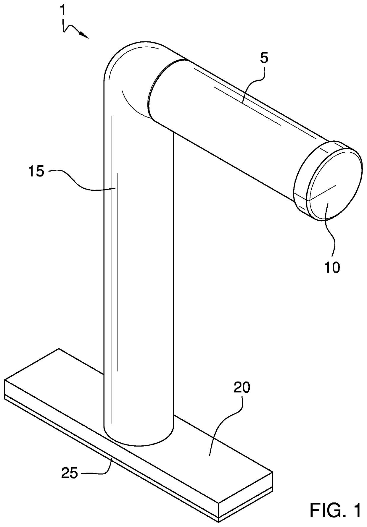
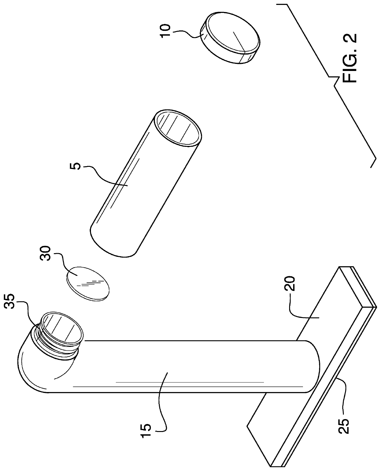
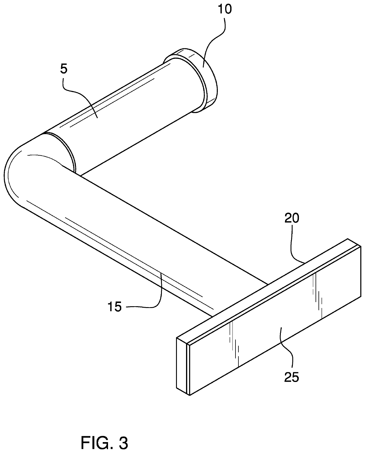
[0023]The device 1 is comprised of a base 20 which has a first side and a second side. On the underside of the first side a magnet 25 is placed so that this device can be mounted on a structure in the field. In FIG. 1 the base is depicted as a rectangle but the base may be a variety of different shapes including circular or a square to name a few. No specific shape is being claimed in this application.

[0024]The purpose of the base is to be able to provide a means to secure the device in the field and also mount a long hollow pipe 15, which ends in an elbow at the end furthest from the base 20.

[0025]At the elbow, which is threaded, a short hollow pipe 5 is mounted. A cap 10 is provided at the end of the short hollow pipe 5. The short hollow pipe 5 has internal threads (not depicted) which mate with the threads 35 on the elbow that are at the end of the long hollow pipe 15.

[0026]An insert 30, is placed within the short hollow pipe 5 such as depicted in FIG. 2. The insert 30 prevents t...


PUM


Abstract

This gauge stand will adhere to a metallic surface in the field so that a technician can hang gauges from the short hollow pipe and work hands free on the equipment to be serviced while at the same time viewing the gauges that are normally used with this type of job. The gauge stand is designed to be portable and should be made to withstand extremes in temperature and all types of environments. A short hollow pipe will enable the technician to store commonly used small items in the short hollow pipe; an insert will be placed in one end of the short hollow pipe to ensure that the small items do not spill out when the device is taken apart.

Description

FIELD OF THE INVENTION[0001]This device will allow a technician in the filed to carry testing equipment to a job site and mount this device temporarily so that the technician can complete the task while using the gauges in the field. It is designed to be portable lightweight while at the same time providing enough room to mount any testing equipment.PRIOR ART[0002]There are references in the prior art that relate to tool storage items. This device will store a few items in a device that will also enable a person to use gauges safely and without incident. A representative example of such a device can be found at Torres U.S. Pat. No. 7,431,313 which is a portable tool storage apparatus system. The Torres device, however, is not very portable and is structurally much different from the current device.[0003]Another example is found at Murray U.S. Pat. No. 9,010,823, which is a socket organizer. It is obviously not used in the AC business but demonstrates some of the prior art regarding ...

Claims


Application Information

Patent Timeline
Patent Type & Authority Patents(United States)
IPC IPC(8): G01D11/30
CPCG01D11/30F16B2200/83
Inventor BARKER, JOHN
Owner BARKER JOHN
Why Eureka
Try Eureka