Cutting tool, mounting bracket, and rotatable cutting head

a cutting tool and mounting bracket technology, applied in cutting machines, ways, constructions, etc., can solve the problems of difficult to remove from the cutting drum and difficult to hammer the bits laterally

Active Publication Date: 2017-02-21
SURFACE PREPARATION TECH
View PDF13 Cites 1 Cited by
  • Summary
  • Abstract
  • Description
  • Claims
  • Application Information

AI Technical Summary

Benefits of technology

[0011]Certain advantages of the embodiments described herein include an ability to vertically insert and remove a cutting tool from a mounting bracket, increased concentration of cutting teeth which provide a smoother cut at increased production speeds, decreased wear on cutting tools, decreased maintenance time between tooth replacements, decreased difficulty in replacing the conical cutting tooth and / or the flat-edged cutting tooth, or a combination thereof.

Problems solved by technology

After the cutting bits have been used to cut pavement they are difficult to remove from the cutting drum due to the high temperature and dust which accumulates on the groove.
Also, it is difficult to hammer the bits laterally because of the tight clearance between the cutting drum and the housing walls.

Method used


Image

  • Cutting tool, mounting bracket, and rotatable cutting head
  • Cutting tool, mounting bracket, and rotatable cutting head
  • Cutting tool, mounting bracket, and rotatable cutting head

Examples


Embodiment Construction

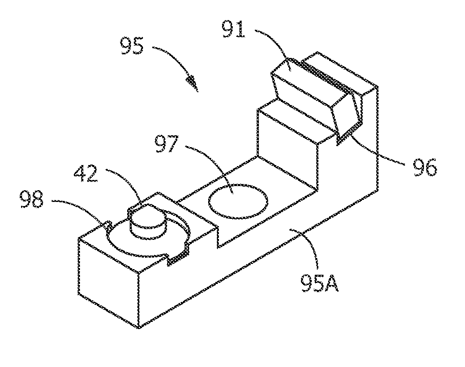
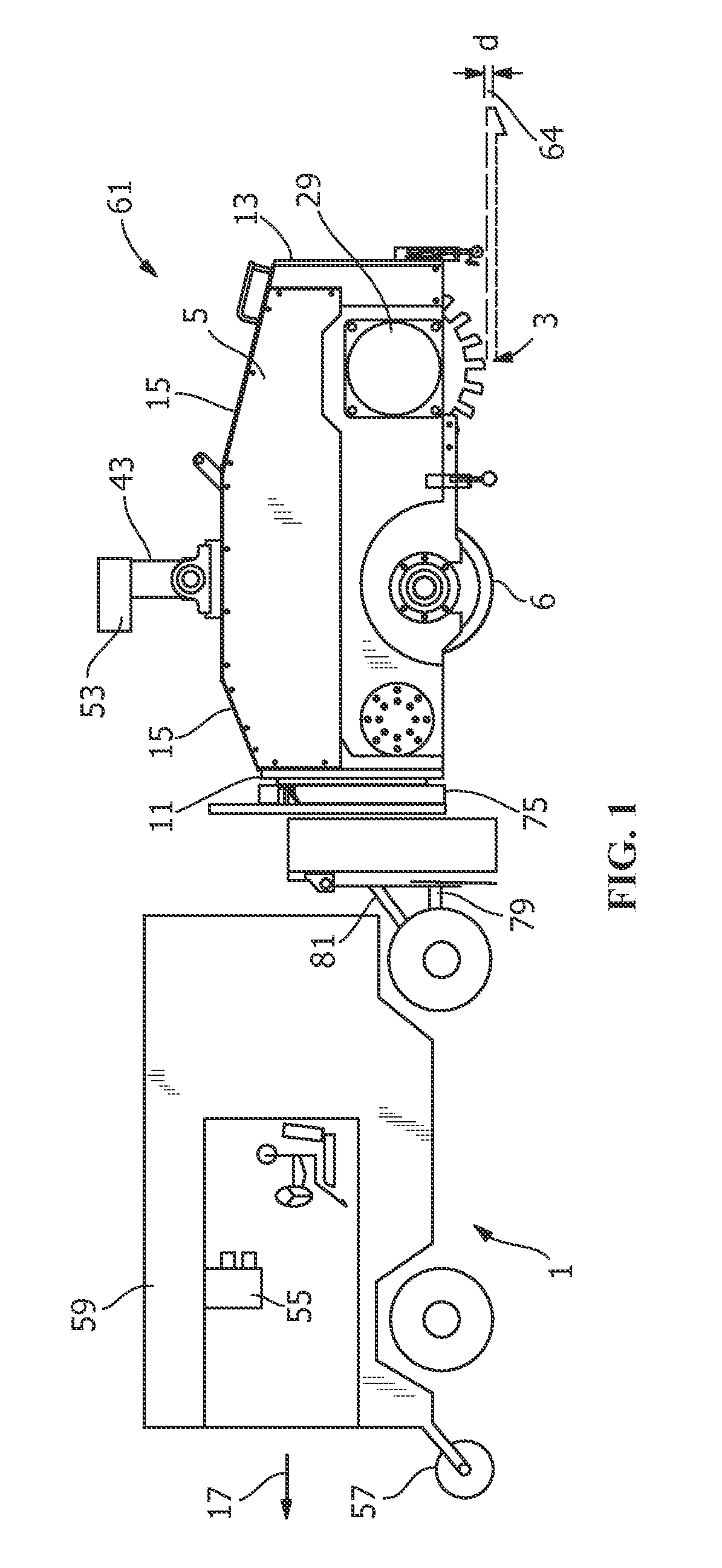
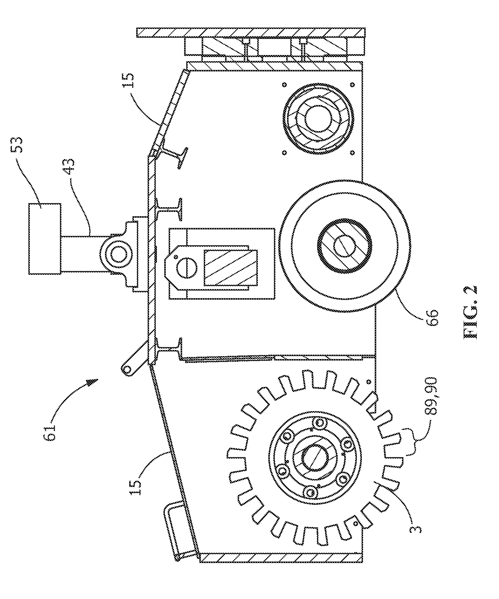
[0030]Referring to FIGS. 1-3, a cutting machine 1 includes a conventional cutting head / drum 3 contained within a drum housing 5 having a pair of opposed, substantially parallel, vertically extending side walls 7 and 9. In addition, drum housing 5 contains front and rear parallel sidewalls 11 and 13, and plates 15 forming part of the top of housing 5. The bottom of housing 5 is substantially open to permit drum 3 to extend therethrough. Drum 3 extending through the bottom of housing 5 provides cutting of a pavement surface 10, removal of existing pavement markings, or any other kind of pavement grinding. For example, as indicated by arrow 17, in one embodiment cutting machine 1 may travel in the forward direction towing drum housing 5 behind it as drum 3 cuts a groove 64 in the pavement surface 10. In an alternate embodiment cutting machine 1 may have drum housing 5 mounted on the front and push drum housing 5 in front of it as drum 3 cuts groove 64 into pavement surface 10. In anoth...


PUM

PropertyMeasurementUnit
depthaaaaaaaaaa
depthaaaaaaaaaa
widthaaaaaaaaaa

Abstract

A cutting tool, a mounting bracket for the cutting tool, and a rotatable cutting head are provided. The cutting tool includes a saddle portion configured to be secured to a mounting bracket, an aperture extending through the saddle portion, and at least one cutting bit attachment portion. The mounting bracket includes a base having a receiving slot configured to receive a cutting tool, a threaded recess extending at least partially through the base, and a curved bottom surface corresponding to a curvature of a cutting drum. The rotatable cutting head comprises a drive shaft connectable to a drive motor, a drum portion coupled to the drive shaft, the drum portion having a curved outer surface, a plurality of mounting brackets secured to the curved outer surface, and at least one cutting tool having at least one cutting bit attachment portion removably secured to at least one of the mounting brackets.

Description

CROSS-REFERENCE TO RELATED APPLICATION[0001]This application claims the benefit of and priority to U.S. Provisional Patent Application No. 61 / 818,740 entitled “Cutting Tool and Mounting Bracket for Rotatable Cutting Head” filed on May 2, 2013, which is hereby incorporated by reference in its entirety.FIELD OF THE INVENTION[0002]The application generally relates to an apparatus for cutting a groove in a pavement surface. The application relates more specifically to a cutting tool, a mounting bracket for the cutting tool, and a rotatable cutting head including the mounting bracket.BACKGROUND OF THE INVENTION[0003]Road surface markings are required on paved roadways to provide signals and information for road traffic. Stripes are typically painted on either side of the road and between traffic lanes to indicate the width of the traffic lanes in which the vehicle can travel. Visibility and uniformity of road markings is important to provide consistency and uncertainty for driver safety....

Claims


Application Information

Patent Timeline
Patent Type & Authority Patents(United States)
IPC IPC(8): E21C35/18B28D1/18E01C23/09
CPCB28D1/186E01C23/0946
Inventor JOHNSON, H. MATTHEWDOWS, JEFFREY M.
Owner SURFACE PREPARATION TECH
Why Eureka
Try Eureka