

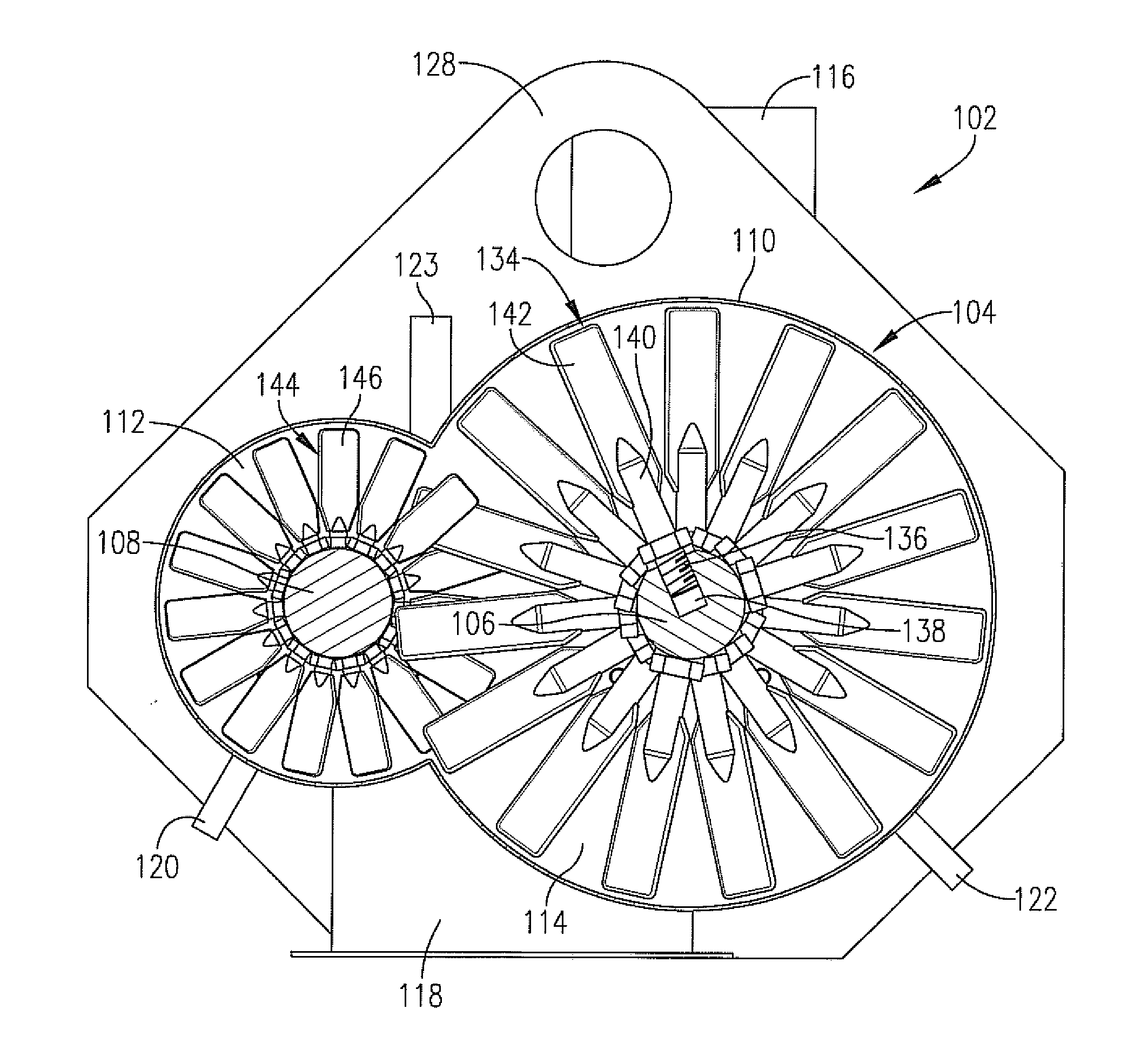
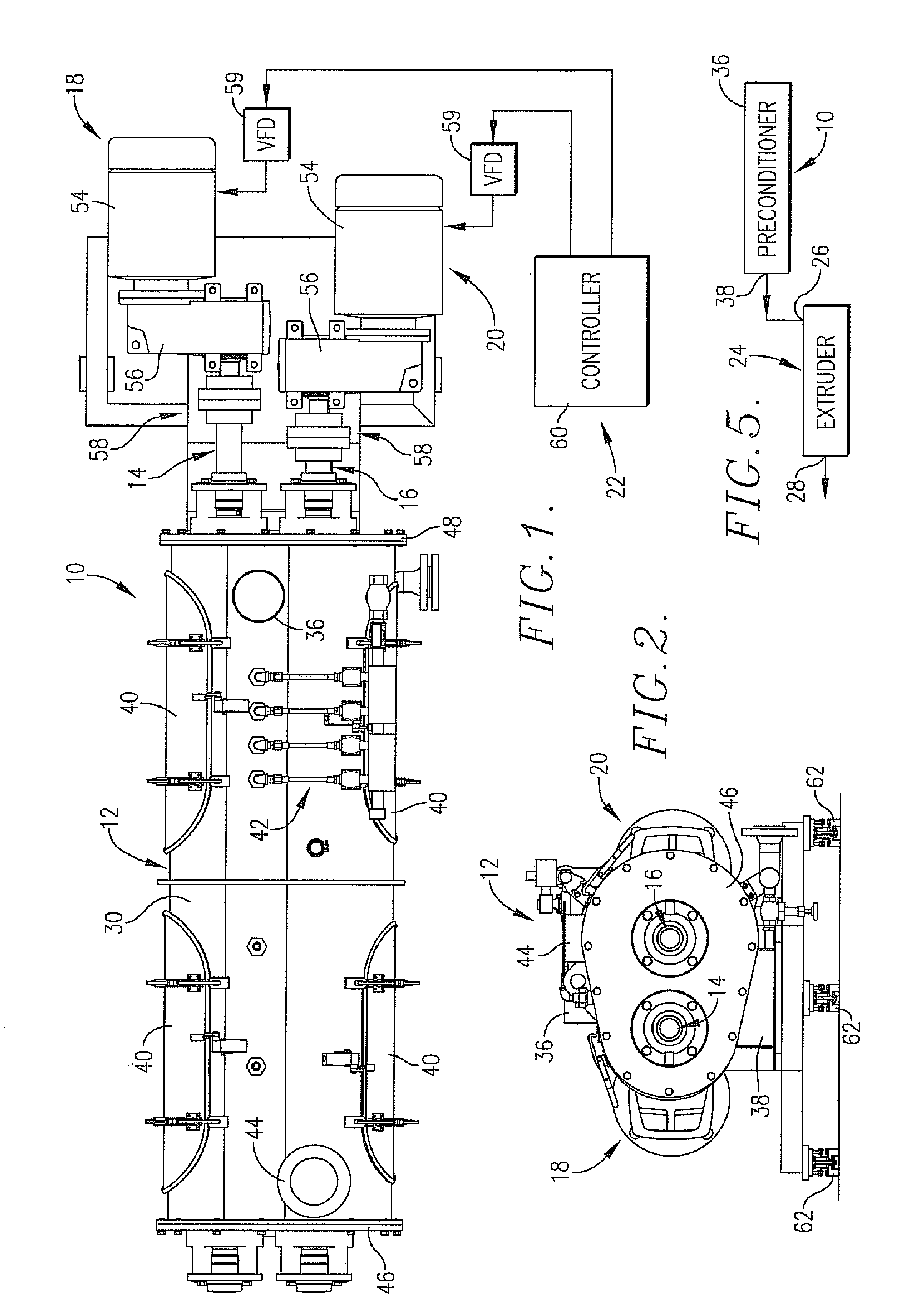
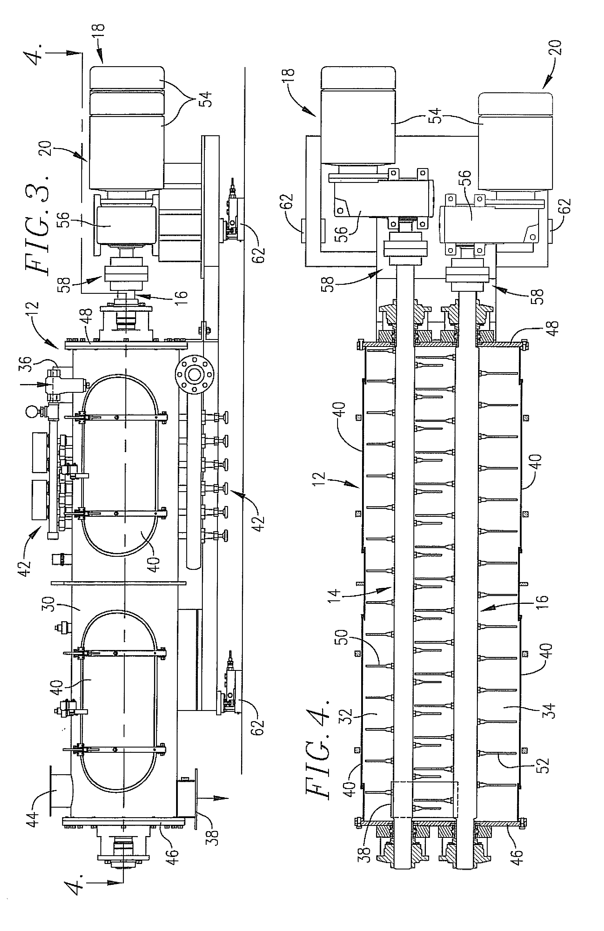
Preconditioner having independently driven high-speed mixer shafts
a high-speed mixer and preconditioner technology, which is applied in the direction of milk preservation, feeding-stuff, other chemical processes, etc., can solve the problems that the preconditioner capable of only limited variability of the residence time is often not suitable for sophisticated pet food processors, cannot be subjected to long retention times in the preconditioner, and cannot be used in such large quantities of fish meal, so as to facilitate easy changes of the retention time
- Summary
- Abstract
- Description
- Claims
- Application Information
AI Technical Summary
Benefits of technology
Problems solved by technology
Method used
Image

Examples
example 1
[0052]In this Example, a standard dog food formulation was prepared and preconditioned using a preconditioner in accordance with the invention. The formulation contained 53.0% corn, 22.0% poultry meal, 15% soybean meal, and 10% corn gluten meal (all percentages by weight). This formulation was fed into the preconditioner inlet and subjected to treatment therein along with injection of steam and water. The small chamber shaft was rotated at a speed of 900 rpm in the reverse direction, whereas the large chamber shaft was rotated at 50 rpm in the forward direction. Three separate tests were conducted at different feed rates to the preconditioner, and the results of these tests are set forth in Table 1 below. As noted in Table 1, the percent cook values obtained using the preconditioner ranged from 47.6-50.9%, and total SME values varied from 1.97-3.49 kW-Hr / Ton.
TABLE 1NameTest 1Test 2Test 3Feed Rate (lbs / hr)5,0009,00010,000Cylinder Water (lbs / hr)8501,6001,700Cylinder Steam (lbs / hr)6101...
example 2
[0053]In this Example, a standard cat food formulation was prepared and preconditioned as set forth in Example 1. The cat food formulation contained 32% poultry meal, 28% corn, 14% rice, 13% corn gluten meal, 3% beat pulp, 2% phosphoric acid (54% H3PO4), and 8% poultry fat (all percentages by weight). In the three separate test runs, the small chamber shaft was rotated at 800 rpm in the reverse direction while the large chamber shaft rotated at 50 rpm in the forward direction. The results of these tests are set forth in Table 2 below, where percent cook varied from 45.8 to 48.1% and total SME values ranged from 2.9 to 3.9 kW-Hr / Ton.
TABLE 2NameTest 4Test 5Test 6Feed Rate (lbs / hr)4,0004,0004,000Cylinder Water (lbs / hr)7607601,140Cylinder Steam (lbs / hr)580580840Cylinder Oil (lbs / hr)2002800DDC Small (L) Shaft DirectionRRR(F or R)DDC Small (L) Shaft Speed (RPM)800800800DDC Small (L) Shaft Load (%)40.0%40.0%42.0%DDC Small (L) HP151515DDC Large (R) Shaft DirectionFFF(F or R)DDC Large (R) Sh...
example 3
[0054]In this Example, a floating aquatic feed formulation used in the manufacture of catfish feeds was prepared and preconditioned as set forth in Example 1. The floating aquatic feed formulation contained 20% whole corn, 20% fish meal, 20% de-fatted rice bran, 15% wheat midlings, 10% soybean meal, 10% beat pulp, and 5% wheat (all percentages by weight). The three separate test runs, the small diameter shaft was rotated at 800 rpm in the reverse direction and the large diameter shaft was rotated at 50 rpm in the forward direction. These results are set forth in Table 3 where it can be seen that the cook varied from 78.7-84.5% and the total SME values were 3.7 kW-Hr / Ton.
TABLE 3NameTest 7Test 8Test 9Feed Rate (lbs / hr)4,0004,0004,000Cylinder Water (lbs / hr)1,2801.3601.520Cylinder Steam (lbs / hr)1,2001,2001.200Cylinder Oil (lbs / hr)000DDC Small (L) Shaft DirectionRRR(F or R)DDC Small (L) Shaft Speed (RPM)800800800DDC Small (L) Shaft Load (%)37.0%37.0%37.0%DDC Small (L) HP151515DDC Large (...
PUM
 Abstract
Description
Claims
Application Information