

In-Ear Headphone
a headphone and in-ear technology, applied in the field ofinear headphone, can solve the problems of not being able to ensure good sound reproduction, not being able to damp the resonance of the in-ear cavity, and not being able to achieve good damping function, good sound reproduction, and easy production of vents
- Summary
- Abstract
- Description
- Claims
- Application Information
AI Technical Summary
Benefits of technology
Problems solved by technology
Method used
Image

Examples
Embodiment Construction
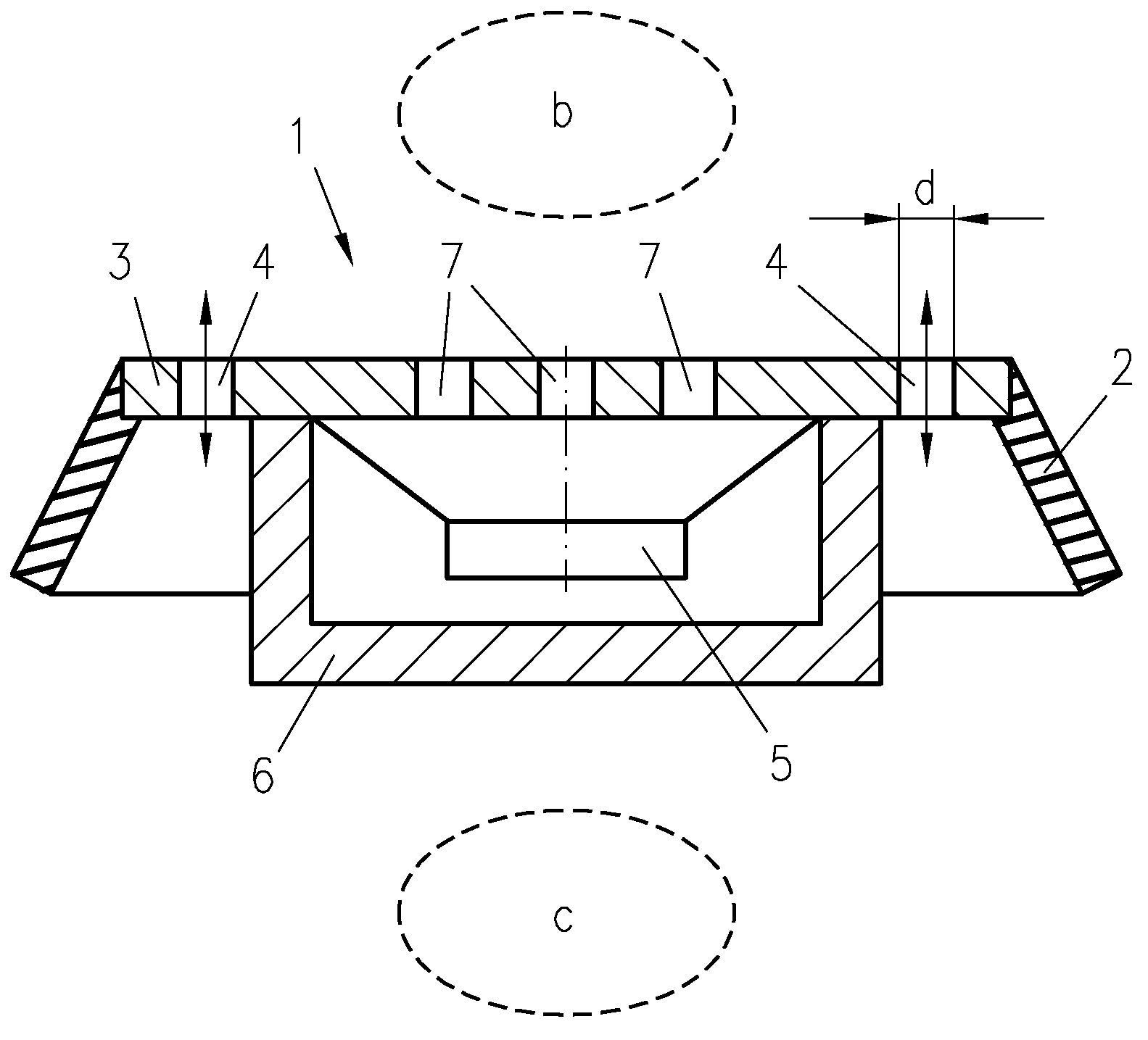
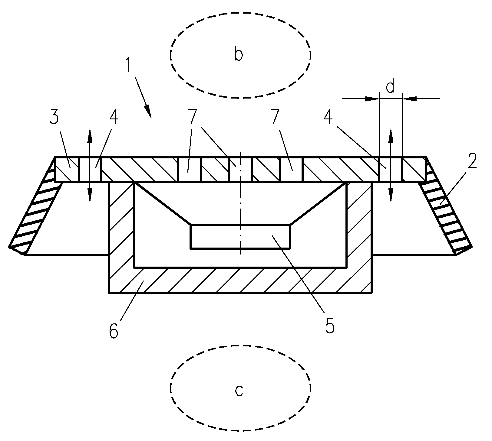
[0015] An in-ear headphone 1 according to the invention comprises an elastic sealing part 2 and a solid sealing part 3 for sealing an ear cavity b against an outside region c. The solid sealing part 3 is manufactured as a solid plate covering the sound radiation side of a loudspeaker 5, which loudspeaker 5 is arranged within a housing 6. Through holes 7 for sound radiation are arranged in a central portion of the plate, while a portion of the plate protruding laterally from the housing 6 comprises damping vents 4. The portion comprising the damping vents 4 forms an edge that radially surrounds the housing 6.
[0016] The central portion comprising the sound radiation through holes 7 and the portion comprising the damping vents 4 may alternatively be formed as separate parts. The solid sealing part 3 is preferably made of plastics.
[0017] The damping vents 4 of the solid sealing part 3 connect the ear cavity b to the outside region c in a mounted state of the in-ear headphone 1, wherei...
PUM
 Abstract
Description
Claims
Application Information