
Blasting system and method

a technology of blasting system and blasting method, which is applied in the direction of combustion process, combustion ignition, incandescent ignition, etc., can solve the problems of insufficient accuracy or readily available gps location data

Inactive Publication Date: 2008-05-01
DETNET SOUTH AFRICA (PTY) LTD
View PDF16 Cites 28 Cited by
  • Summary
  • Abstract
  • Description
  • Claims
  • Application Information

AI Technical Summary

Benefits of technology

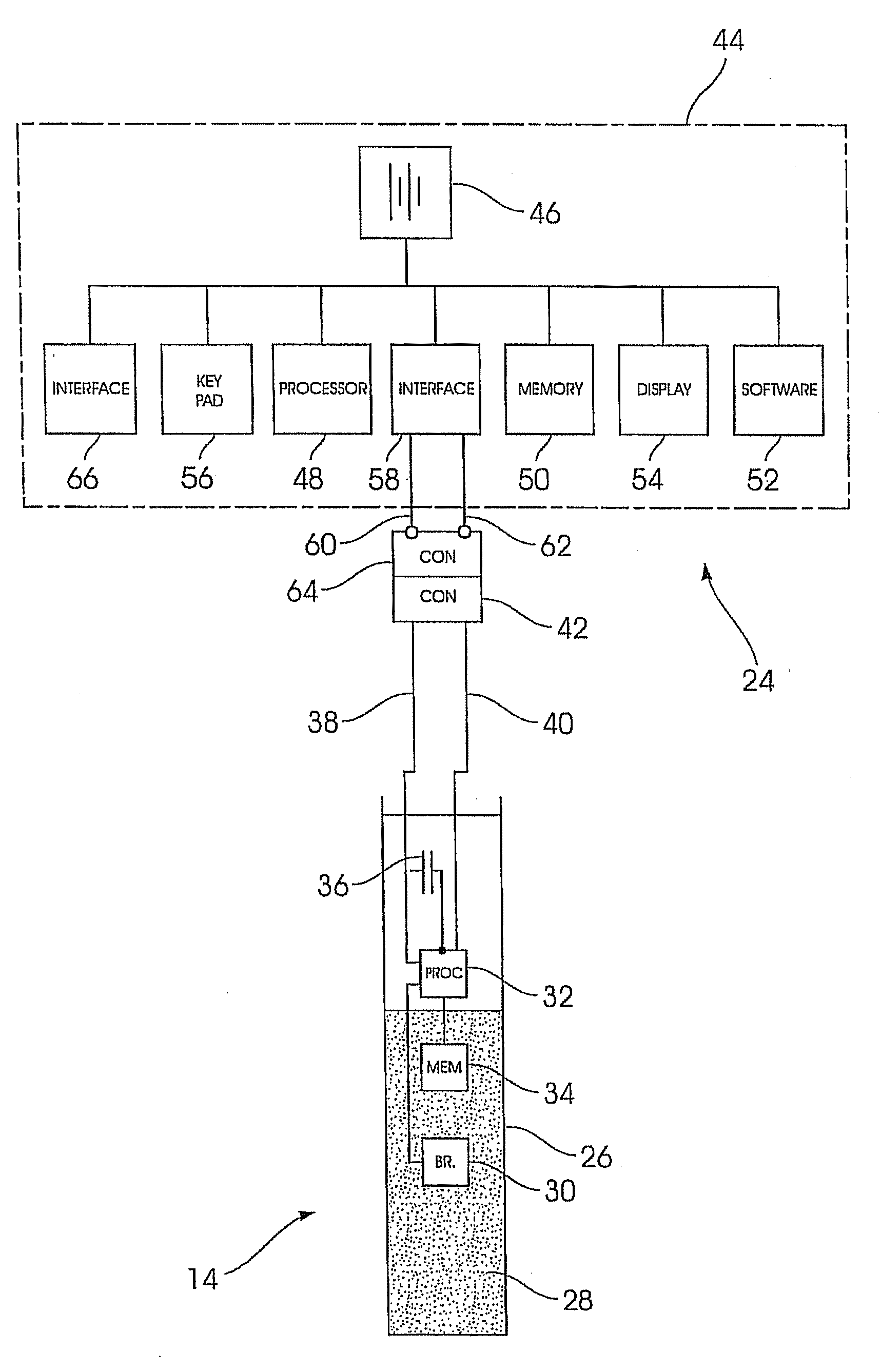
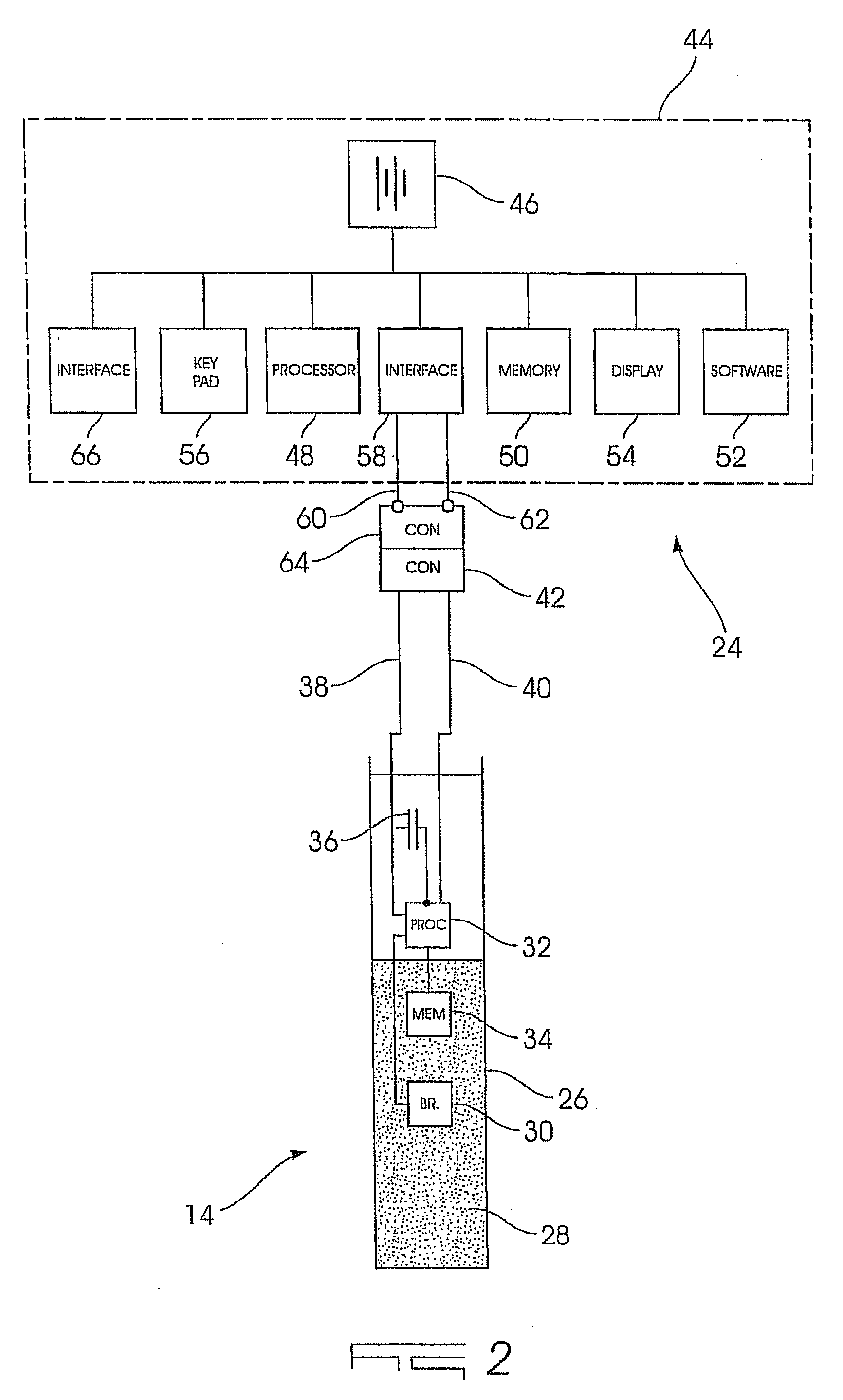
[0032]The control unit may include communication means for receiving data or signals from, and for transferring data or signals to, by wireless links (radio frequencies, infrared etc.) or via physical links (wire, fibre optic cable etc.), the portable device referred to or one or more of the detonators.
[0033]The control unit may include a housing, a control memory in which are stored firing time information for each of a plurality of detonators in the array and a respective identity code for each of the detonators, each identity code being dependent at least on the location of the respective detonator in the array, and a two-connection interface for transferring the firing time information to the respective detonators.

Problems solved by technology

A further factor is that GPS location data may not be sufficiently accurate or readily available, due for example to a rock wall or rock body which blocks reception of a GPS signal.

Method used


Image

  • Blasting system and method
  • Blasting system and method
  • Blasting system and method

Examples


Embodiment Construction

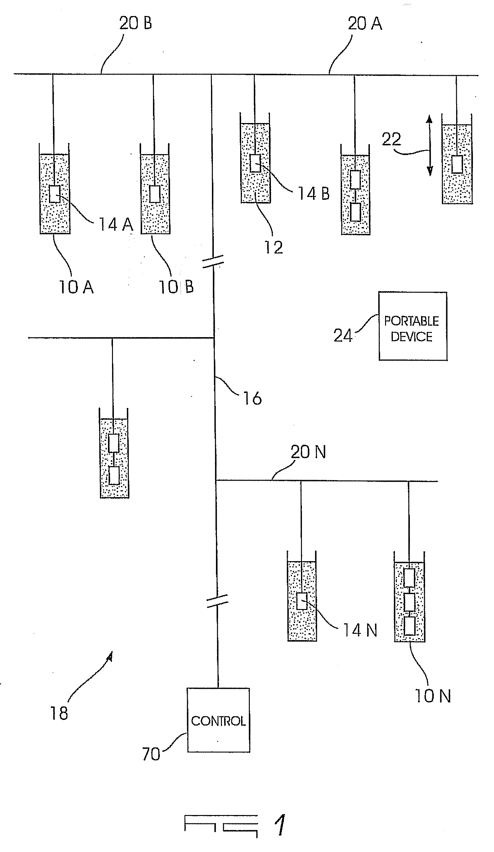
[0039]FIG. 1 of the accompanying drawings illustrates a number of boreholes 10A, 10B . . . 10N respectively formed at predetermined positions in the ground using conventional techniques. The depth of a borehole and its size may vary according to requirements known in the art.

[0040]Each borehole contains explosive material 12 and at least one respective detonator 14A, 14B . . . 14N.

[0041]A two-wire harness 16 is used to connect the detonators to one another in an array 18 which is defined by rows of detonators 20A, 20B, 20N and, within each row 20, the boreholes 10A, 10B . . . which are in the row. The array can be further particularised by the number of detonators in a borehole. As is shown in FIG. 1 most of the boreholes contain one detonator but a limited number contain two detonators and one borehole contains three detonators. A number can be assigned to each detonator when they are decked or stacked in this way and this feature also characterises the blast array. Apart from the ...


PUM


Abstract

The invention provides a blasting system which includes a plurality of electronic detonators which are configured in a blast array which has at least one row and a plurality of detonators in the row, each detonator including a memory in which is stored at least a respective identity code which is dependent, at least, on the row on which the detonator is, and on the detonator's position in the row, a harness which interconnects the detonators, and at least one control unit, connected to the harness, which generates a signal to fire the detonators.

Description

BACKGROUND OF THE INVENTION[0001]This invention relates to a blasting method which makes use of electronic detonator.[0002]In one respect electronic blasting systems can be divided into systems which are implemented using two wires which interconnect the detonators, and systems which make use of more than two wires.[0003]In a system of the former kind blast times for the various detonators are usually assigned while a blaster is working at a blasting bench.[0004]In a multi-wire system (of the latter kind) the additional wires allow the connection order of the detonators to be established and the wiring order can be used to determine blast timing factors. This type of system can be easier to use as the blaster can readily configure the blast pattern in terms of inter-detonator and inter-row timing increments.[0005]Some blasting systems make use of a location system such as a global positioning system (GPS) to collate the identity of a particular detonator with a geographical location...

Claims


Application Information

Patent Timeline
Patent Type & Authority Applications(United States)
IPC IPC(8): F42B3/00
CPCF42D1/055
Inventor LABUSCHAGNE, ALBERTUS ABRAHAMKOEKEMOER, ANDRE LOUISSCHLENTER, CRAIG CHARLES
Owner DETNET SOUTH AFRICA (PTY) LTD
Learn More