System and method for fast mr coil sensitivity mapping

a technology of sensitivity mapping and mr coil, applied in the field of magnetic resonance imaging, can solve the problems of overall scan time and patient throughput decline, and achieve the effect of rapid coil sensitivity mapping

Active Publication Date: 2008-05-01
GENERAL ELECTRIC CO
View PDF3 Cites 48 Cited by
  • Summary
  • Abstract
  • Description
  • Claims
  • Application Information

AI Technical Summary

Benefits of technology

[0010]The present invention provides for rapid coil sensitivity mapping for MR systems using computer-developed normalization or weighting functions. Neural networks or similar computer intelligence are exemplary techniques employed to generate the weighting functions, further allowing computers to construct coil sensitivity profiles for each coil of an RF coil assembly with minimal input data.

Problems solved by technology

However, as the number of calibration or sensitivity-measuring scans required to produce this pixel by pixel fit is increased, overall scan time and patient throughput decrease.

Method used


Image

  • System and method for fast mr coil sensitivity mapping
  • System and method for fast mr coil sensitivity mapping
  • System and method for fast mr coil sensitivity mapping

Examples


Embodiment Construction

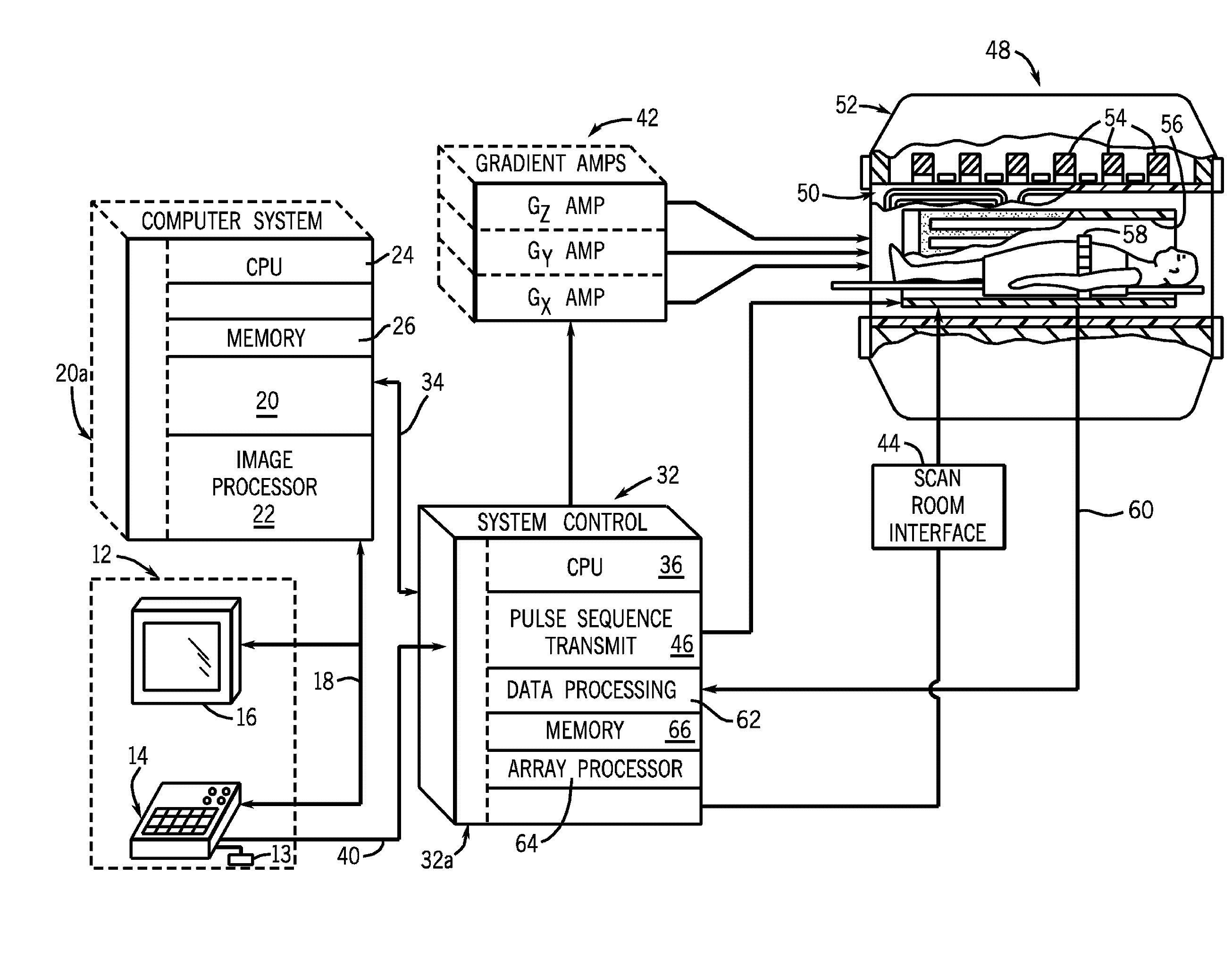
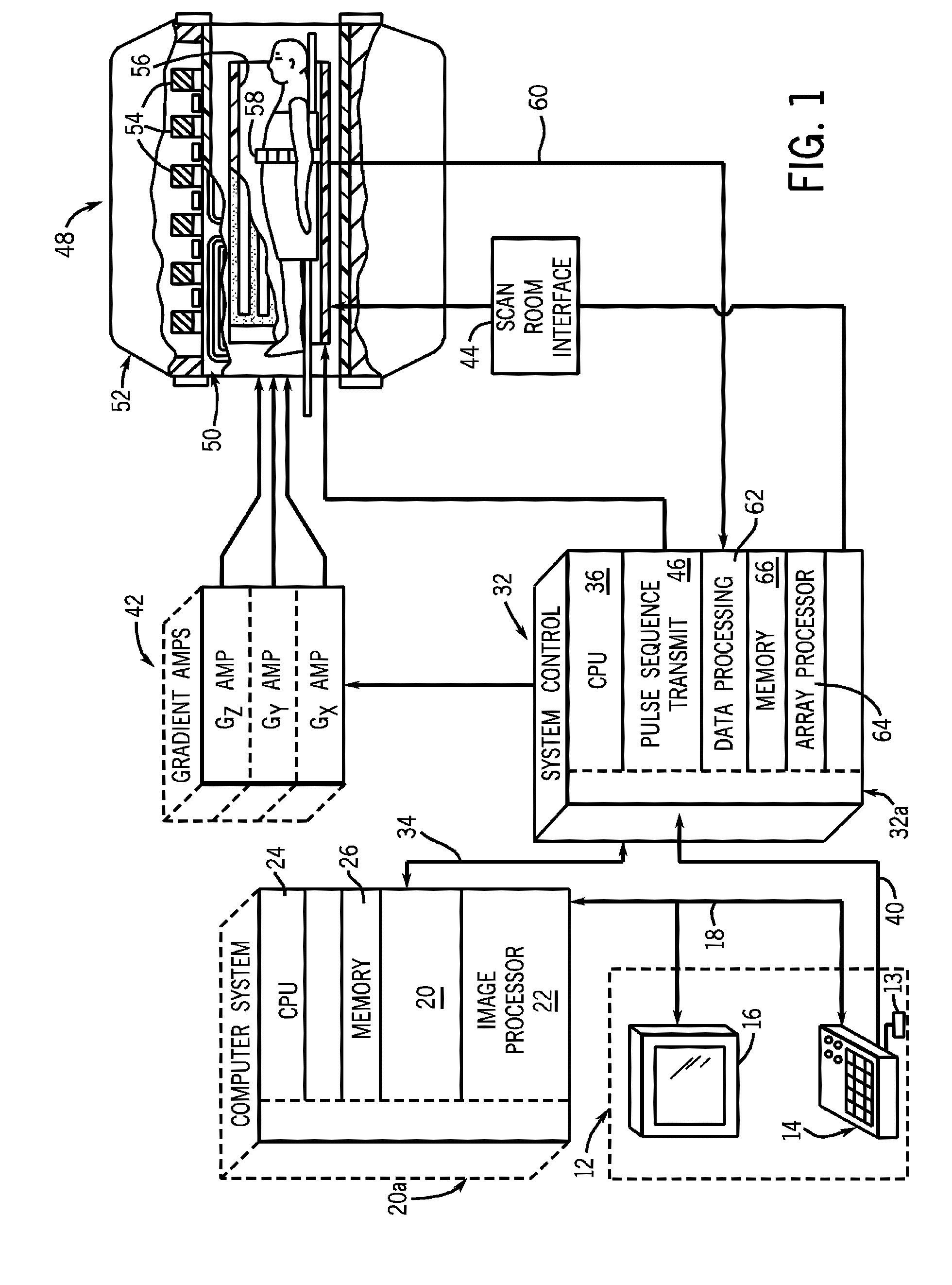
[0021]Referring to FIG. 1, the major components of an example magnetic resonance imaging (MRI) system incorporating the present invention are shown. The operation of the system may be controlled from an operator console 12 which includes a keyboard or other input device 13, a control panel 14, and a display screen 16. The input device 13 can include a mouse, keyboard, track ball, touch activated screen, light wand, or any similar or equivalent input device, and may be used for interactive geometry prescription. The console 12 communicates through a link 18 with a separate computer system 20 that enables an operator to control the production and display of images on the display screen 16. The computer system 20 includes a number of modules which communicate with each other through a backplane 20a. These include an image processor module 22, a CPU module 24 and a memory module 26, which may include a frame buffer for storing image data arrays. The computer system 20 may also be connec...


PUM


Abstract

A system and method for mapping the sensitivity of MR coils includes a neural network or other computer intelligence trained from sample MR data to determine coil sensitivity profiles or sensitivity normalizations. Once the network is trained, subsequent coil mapping determinations may include fewer mapping acquisitions per coil. The resulting sensitivity map can be used in compensating for B1 inhomogeneities, parallel imaging reconstruction, generating tailored excitation currents for each individual coil, RF shimming, or other processes.

Description

BACKGROUND OF THE INVENTION[0001]The present invention relates generally to magnetic resonance imaging, and more specifically, to a system and method for mapping the sensitivity of radio frequency (RF) coils of a magnetic resonance (MR) system. The invention finds particular utility in parallel imaging applications by providing quickly determined coil sensitivity maps, requiring fewer flip angles / scans to determine.[0002]When a substance such as human tissue is subjected to a uniform magnetic field (polarizing field B0), the individual magnetic moments of the spins in the tissue attempt to align with this polarizing field, but precess about it in random order at their characteristic Larmor frequency. If the substance, or tissue, is subjected to a magnetic field (excitation field B1) which is in the x-y plane and which is near the Larmor frequency, the net aligned moment, or “longitudinal magnetization”, Mz, may be rotated, or “tipped”, into the x-y plane to produce a net transverse ...

Claims


Application Information

Patent Timeline
Patent Type & Authority Applications(United States)
IPC IPC(8): G01V3/00
CPCG01R33/246G01R33/10
Inventor HANCU, ILEANA
Owner GENERAL ELECTRIC CO
Why Eureka
Try Eureka