
Reinforced packing tape with tamper indicator

a technology of reinforced packing tape and tamper indicator, which is applied in the field of reinforced packing tape with tamper indicator, can solve the problems of degradation or destruction of the tamper indicator pattern

Inactive Publication Date: 2008-05-01
STEINZOR ERIC
View PDF16 Cites 5 Cited by
  • Summary
  • Abstract
  • Description
  • Claims
  • Application Information

AI Technical Summary

Benefits of technology

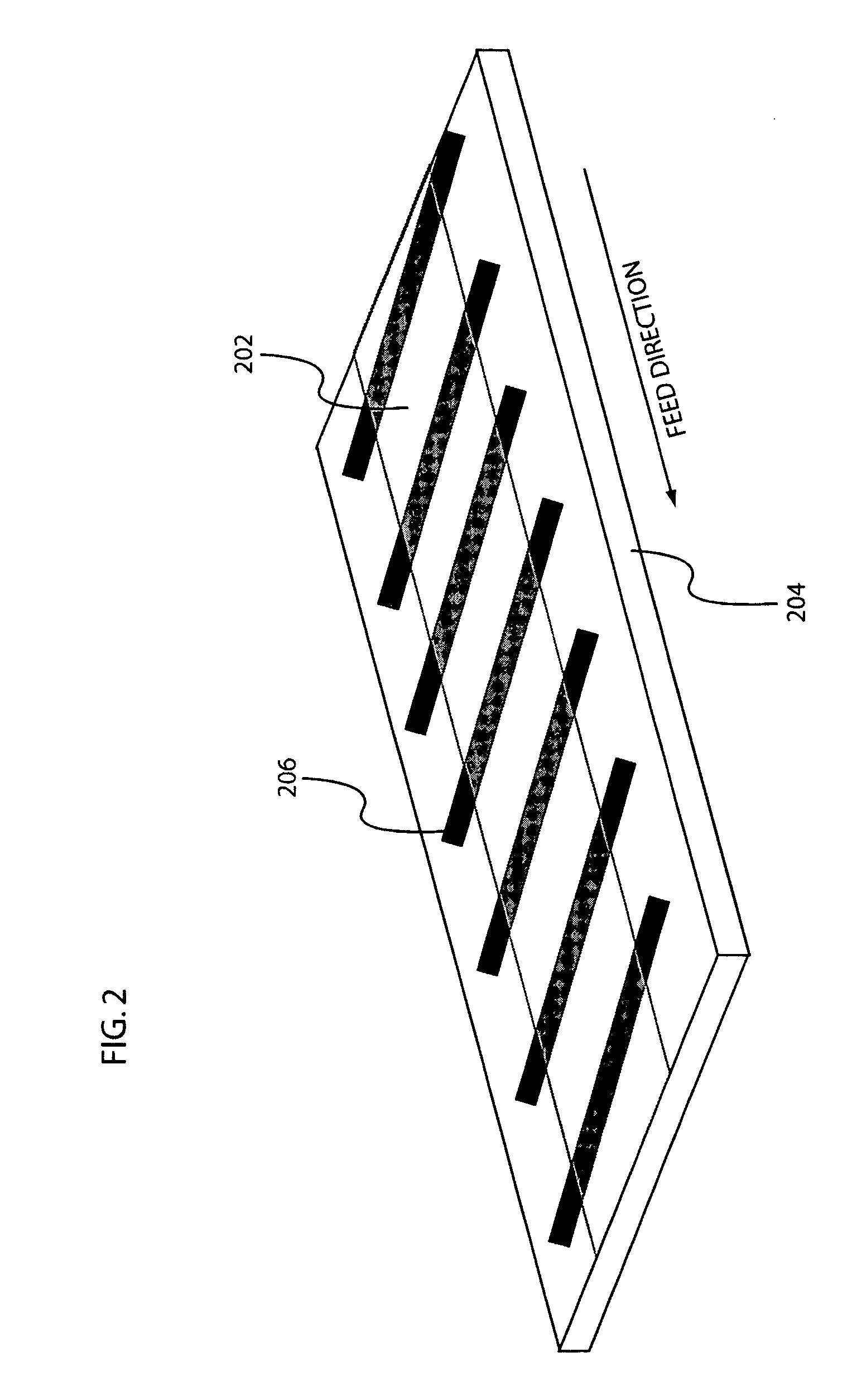
[0011]The tamper indicator pattern may be a stock pattern, such as thick diagonal lines spanning the width of the kraft paper layer, or custom pattern, such as a corporate logo, company / organization name, etc. Preferentially, the tamper indicator pattern is wider than and partially overlaid by the plastic film. Thus, attempts to remove the reinforcing strip results in degradation or destruction of the tamper indicator pattern.
[0012]Additionally, the present invention a packing tape is disclosed having a base layer formed of paper, the base layer having an upper surface and a lower surface; a water-activated adhesive coating applied to the lower surface of the base layer; a tamper indicator pattern imprinted on the upper surface of the base layer; and a transparent reinforcing film, the reinforcing film being disposed on and bonded to the upper surface of the base layer.
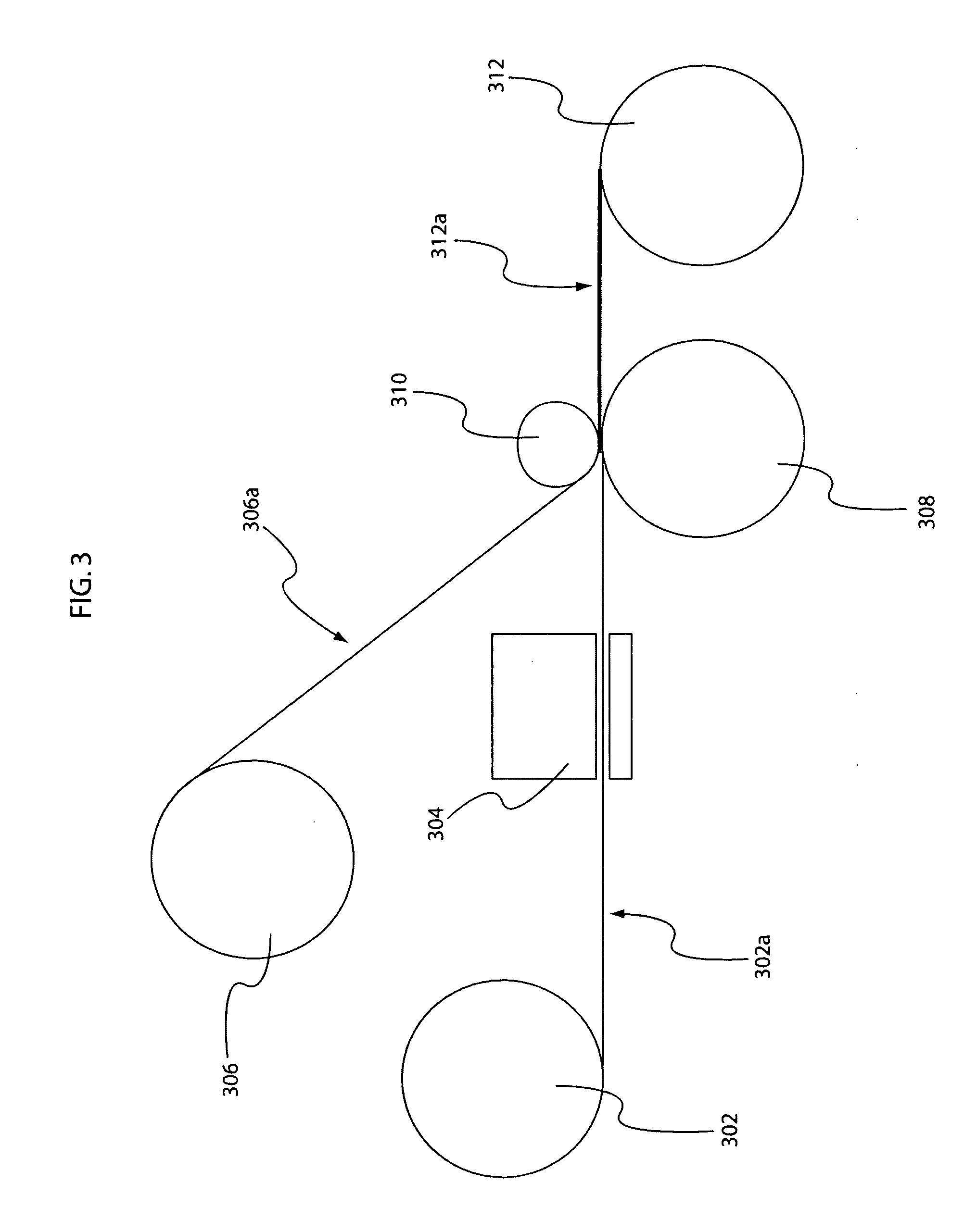
[0013]Further, the present invention provides a method for manufacturing a reinforced packing tape with tamper indication as well. The manufacturing method includes providing a first roll of kraft paper having a lower surface coated with a water-activated adhesive; and providing a second roll of a reinforcing film having a lower surface coated with a strong paper / plastic adhesive. The kraft paper forms a base layer of the reinforced packing tape. The method further includes printing a tamper indicator pattern on an upper surface of the kraft paper and joining the printed kraft paper with the reinforcing film. The joining step bonds the lower surface of the reinforcing film to the upper surface of the printed kraft paper.

Problems solved by technology

Thus, attempts to remove the reinforcing strip results in degradation or destruction of the tamper indicator pattern.

Method used


Image

  • Reinforced packing tape with tamper indicator
  • Reinforced packing tape with tamper indicator
  • Reinforced packing tape with tamper indicator

Examples


Embodiment Construction

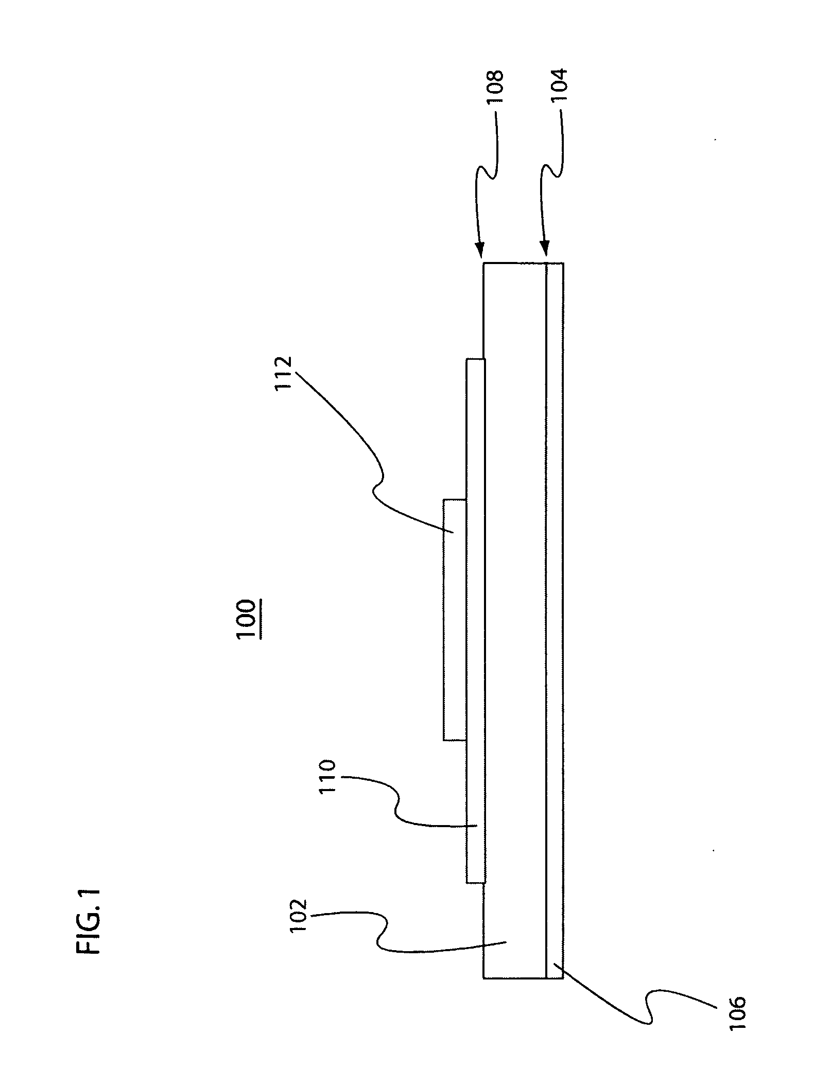
[0018]Referring to FIG. 1, a cross-section view representing a reinforced tape 100 in accordance with an embodiment of the present invention is shown. The reinforced tape 100 is formed of a base layer 102 of kraft paper. A lower surface 104 of the base layer 102 is coated with a water-activated adhesive 106. An upper surface 108 of the base layer 102 is imprinted with a tamper indicator pattern 110. The base layer 102 may be dimensioned between 3 and 6 inches wide. However, other standard packing tape widths may be used as well. Preferentially, the base layer is 60 lb kraft paper, however any weight paper between 35 lb and 90 lb may be used.

[0019]It should be noted that the reinforced tape 100 and its constituent components are not shown to scale in FIG. 1. Rather the scale of the individual components of the reinforced tape 100 is exaggerated to provide easier identification of the relation of the components to one another. Thus, the tamper indicator pattern 110 is preferentially f...


PUM

PropertyMeasurementUnit
weightaaaaaaaaaa
weightaaaaaaaaaa
weightaaaaaaaaaa

Abstract

A reinforced packing tape having a tamper indicator is disclosed. The reinforced packing tape is constructed of a base layer of kraft paper having a lower surface coated with a water-activated adhesive and an upper surface printed with a tamper indicator pattern. A portion of the tamper indicator pattern is overlaid with a reinforcing film of transparent plastic. The plastic film is strongly bonded to the base layer such that when an attempt to remove the plastic film is made, the tamper indicator pattern is altered, degraded or destroyed; thus, a tamper attempt is indicated.

Description

I. FIELD OF THE INVENTION[0001]The present invention relates generally to packaging tape. More specifically, the present invention relates to a reinforced packing tape having a tamper indicator and method for manufacturing the same.II. BACKGROUND OF THE DISCLOSURE[0002]Adhesive tapes for sealing cartons or carton flaps during manufacture or after the carton is filled are well known in the art. One of the most common constructions is a standard kraft paper tape, which includes a water-soluble or water activated adhesive on one side. Rolls of this tape can be dispensed through machines, which rely on the longitudinal stiffness of the tape to unwind it from the roll and force it through a tape-moisturizing component. This component includes a water reservoir, which moistens the adhesive surface of the tape and readies it for application to the carton. Often, the tape-moisturizing component includes a heating bar, which enhances the activation of the moistened adhesive through the use o...

Claims


Application Information

Patent Timeline
Patent Type & Authority Applications(United States)
IPC IPC(8): B41M3/02C09J7/29
CPCC09J7/0296C09J7/042C09J2203/338C09J2400/283Y10T428/24802C09J2427/006Y10S428/916Y10T428/28C09J2423/006C09J7/29C09J7/21C09J7/32
Inventor STEINZOR, ERIC
Owner STEINZOR ERIC
Learn More