
Hinge with simplified components

Inactive Publication Date: 2008-05-15
SHIN ZU SHING
View PDF14 Cites 1 Cited by
  • Summary
  • Abstract
  • Description
  • Claims
  • Application Information

AI Technical Summary

Benefits of technology

[0006]The main objective of the present invention is to provide a hinge with simplified components. The hinge with simplified components has a central bracket, a first tilt hinge assembly, a second tilt hinge assembly and a rotating hinge assembly. The central bracket has a main arm, a first arm and a second arm. The first and second arms are formed respectively on two ends of the main arm. The first and second tilt hinge assemblies respectively connect to the first and second arms. The rotating hinge assembly connects to the main arm. The second tilt hinge assembly has a barrel with multiple steps formed on an outer wall of the barrel. The diameters of the steps are reduced from an inner end to an outer end of the barrel. The steps formed on the outer wall of the barrel replace many spacers. Therefore, the components of the hinge in accordance with the present invention are simplified and then the manufacturing cost and the assembling complexity are decreased.

Problems solved by technology

However, many spacers increase manufacturing cost and cause assembling complexity.

Method used


Image

  • Hinge with simplified components
  • Hinge with simplified components
  • Hinge with simplified components

Examples


Embodiment Construction

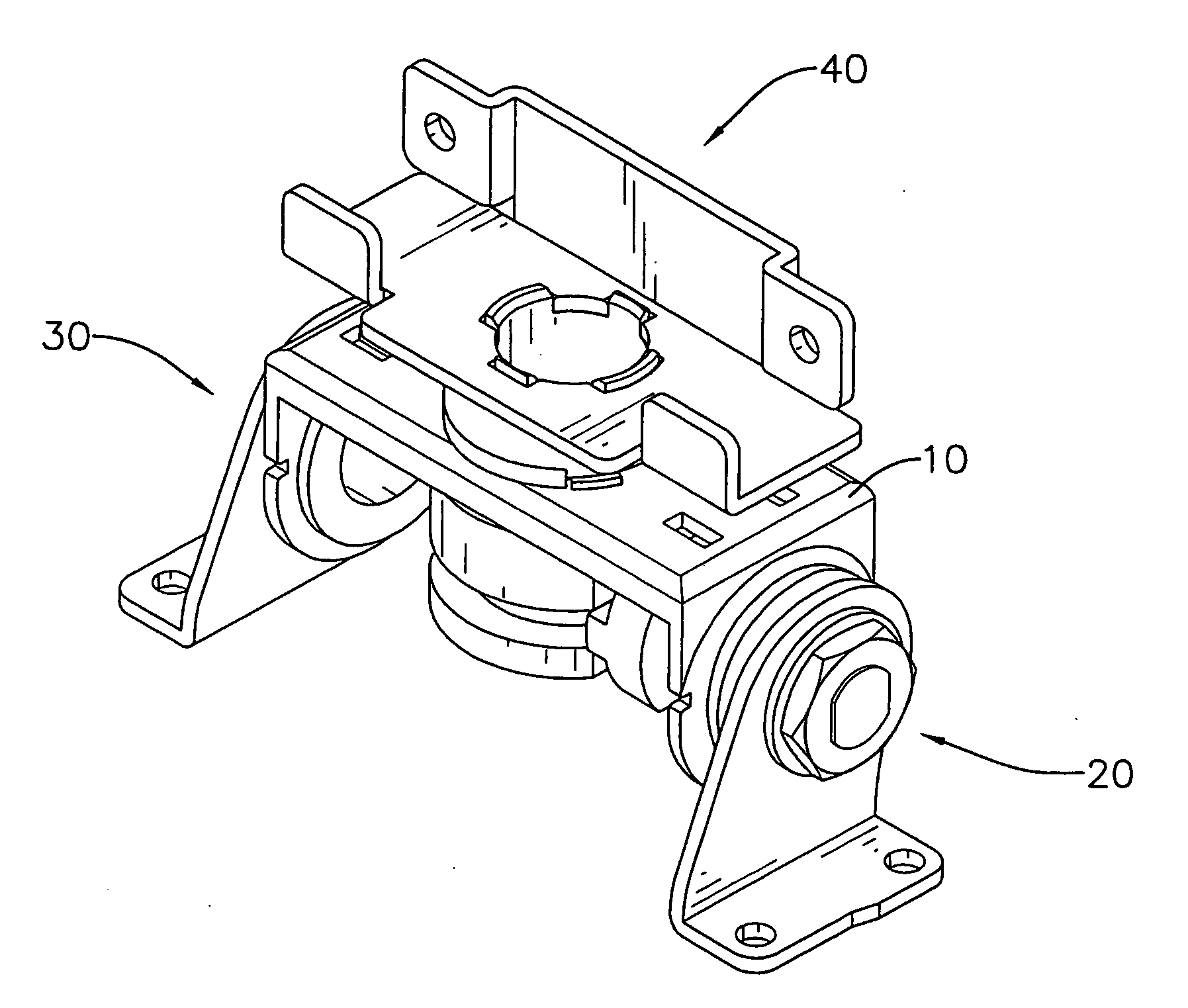
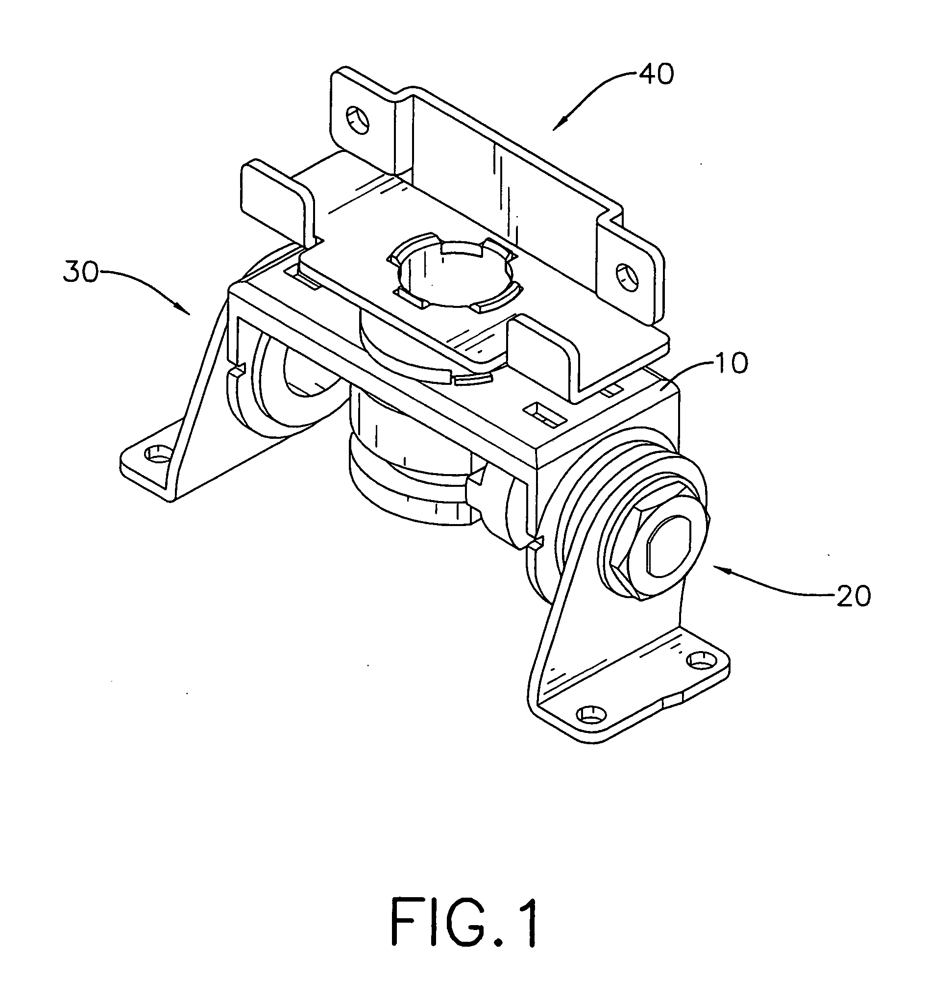
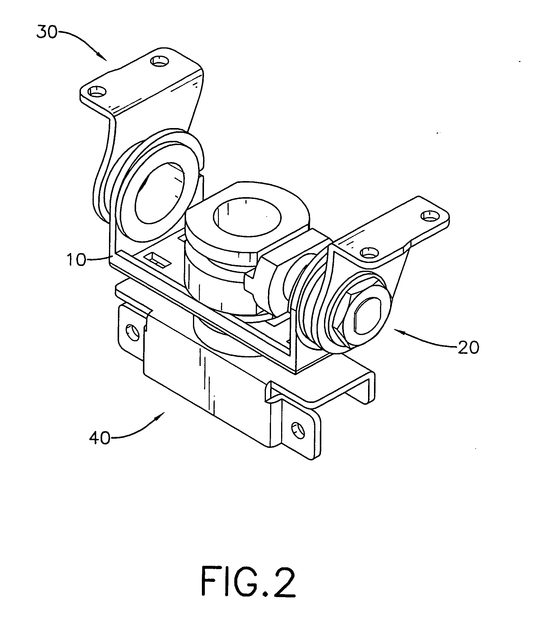
[0024]With reference to FIGS. 1 and 2, a hinge in accordance with the present invention comprises a central bracket (10), a first tilt hinge assembly (20), a second tilt hinge assembly (30) and a rotating hinge assembly (40).

[0025]With reference to FIGS. 3 and 4, the central bracket (10) is U-shaped and comprises a main arm (11), a first arm (12) and a second arm (13).

[0026]The main arm (11) has a first end, a second end, an inner surface, an outer surface, two sides, a circular central hole (111), two ribs (112), an annular recess (115), at least one positioning detent (113), at least one limiting protrusion (114). The ribs (112) are respectively and perpendicularly formed on the two sides of the main arm (11) and extend from the inner surface. The annular recess (115) is formed in the inner surface of the main arm (11) around the central hole (111). The at least one positioning detent (113) is formed in the annular recess (115). The at least one limiting protrusion (114) is formed...


PUM


Abstract

A hinge with simplified components has a central bracket, a first tilt hinge assembly, a second tilt hinge assembly and a rotating hinge assembly. The central bracket has a main arm, a first arm and a second arm. The first and second arms are formed respectively on two ends of the main arm. The first and second tilt hinge assemblies respectively connect to the first and second arms. The rotating hinge assembly connects to the main arm. The second tilt hinge assembly has a barrel with multiple steps formed on an outer wall of the barrel. The diameters of each step are smaller from an inner end to an outer end of the barrel. The steps formed on the outer wall of the barrel replace many spacers. Therefore, the components of the hinge are simplified and then the manufacturing cost and the assembling complexity are decreased.

Description

BACKGROUND OF THE INVENTION[0001]1. Field of the Invention[0002]The present invention relates to a hinge, especially to a hinge with simplified components mounted between a cover and a base of an electronic appliance.[0003]2. Description of the Prior Arts[0004]Electrical appliances such as notebook computers, cell phones, etc. have a cover, a base and a conventional hinge. The conventional hinge connects the cover to the base along a transverse axis and a longitudinal axis to allow the cover to pivot relative to the base. To keep the electronic appliance from damaging when the cover is pivoted relative to the base, the conventional hinge comprises many spacers having corresponding structures to provide positioning and limiting functions. However, many spacers increase manufacturing cost and cause assembling complexity.[0005]To overcome the shortcomings, the present invention provides a hinge with simplified components to mitigate or obviate the aforementioned problems.SUMMARY OF THE...

Claims


Application Information

Patent Timeline
IPC IPC(8): E05D7/00
CPCE05D3/10E05Y2900/606Y10T16/52G06F1/1681G06F1/162E05Y2999/00
Inventor HSU, JIA-HAOLU, AN-DI
Owner SHIN ZU SHING
Learn More