
Rachet wrench

Active Publication Date: 2012-07-26
YANG CHENG PU
View PDF2 Cites 7 Cited by
  • Summary
  • Abstract
  • Description
  • Claims
  • Application Information

AI Technical Summary

Benefits of technology

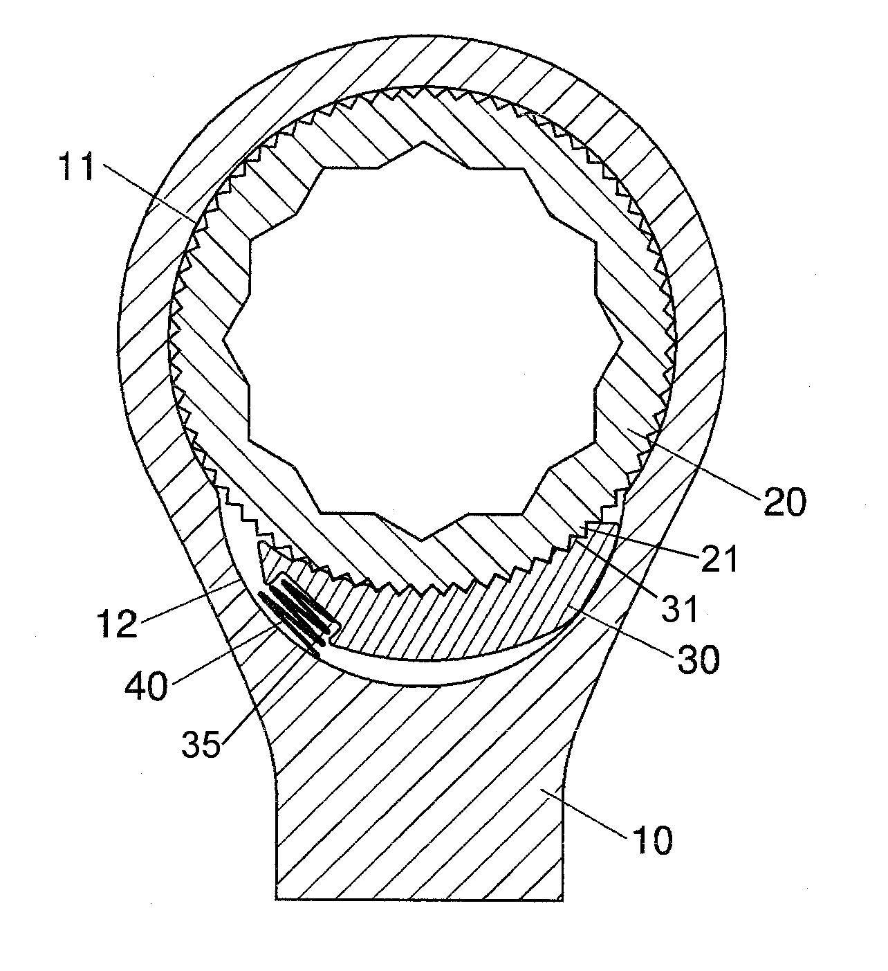
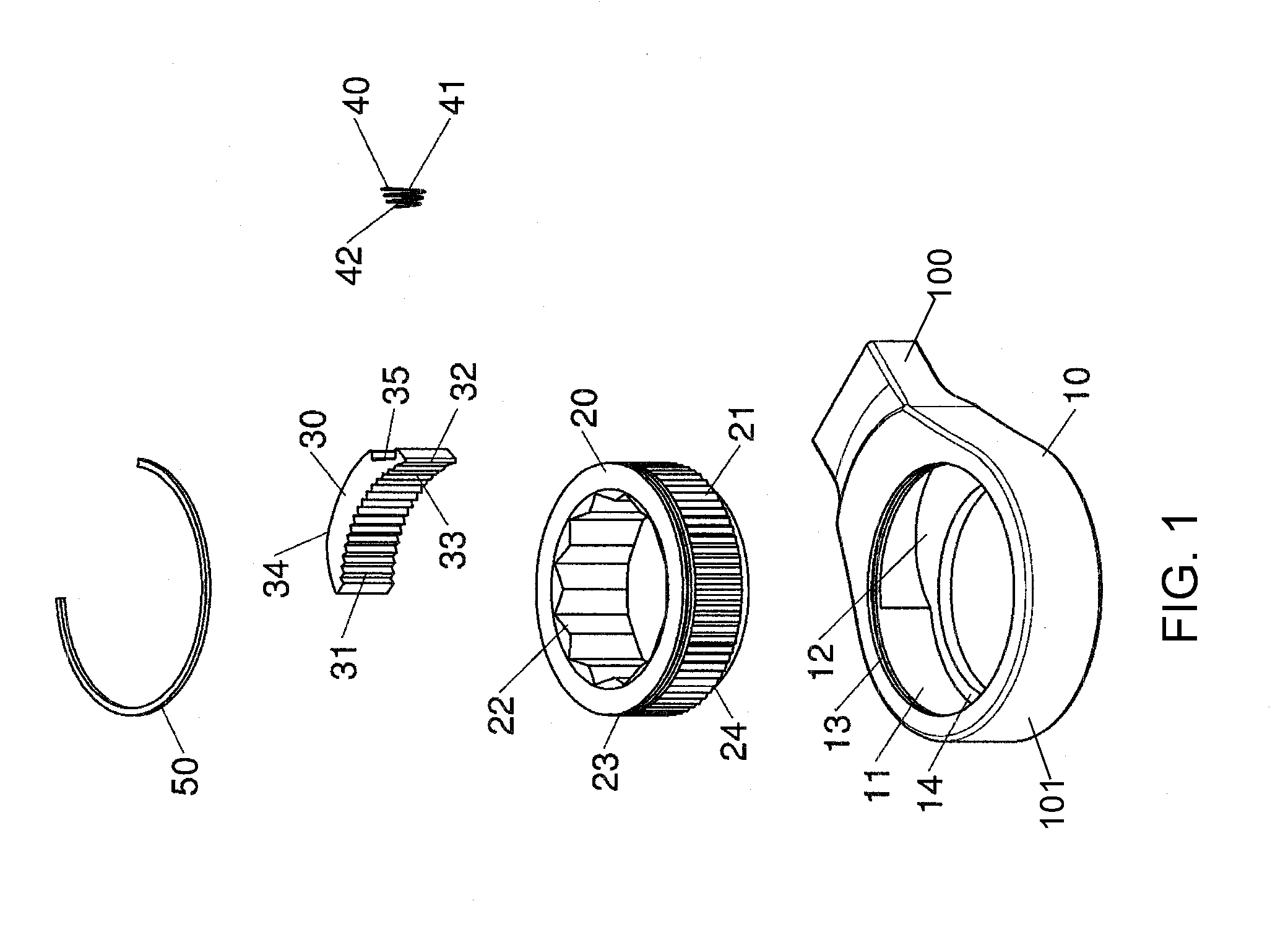
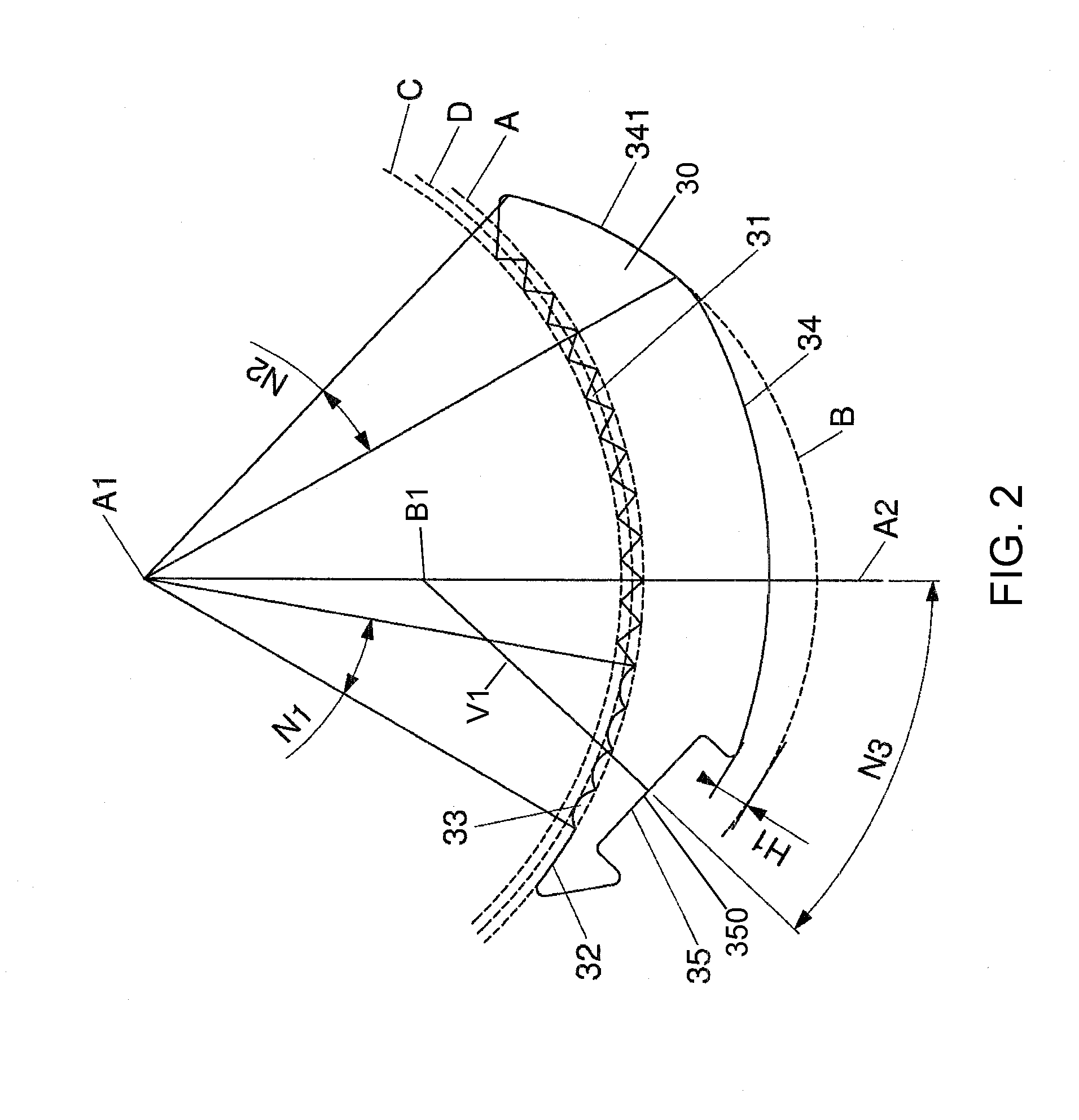
[0008]The object of the present invention is to provide a single direction ratchet wrench which has improved effectiveness of single direction control and also has advantages of simplified components, easier assembly and reduced cost. In order to achieve the foregoing object, a ratchet wheel comprises a main body, a ratchet wheel, a pawl, an elastic element and a C-shape clip. The function end of the main body has a first housing and a second housing for the ratchet wheel and the pawl to be confined within respectively. There is a clamping trough and an annular groove notched at the top and the bottom peripheries of the ratchet wheel respectively. The clamping trough is exactly paired with an annular trough for the clip to clamp and the annular groove allows an annular flange to be engaged, at the bottom of the first housing, for the ratchet wheel to be rotatably lodged within the first housing. A plurality of first retaining cogs, curved second retaining cogs and a first concave surface are successively arranged on the front side of the pawl, and they are distributed along a first arc. The central angle of the second retaining cogs extended along the first arc is less than or equal to 20 degrees. On the rear side of the pawl is a first convex surface whose one end extends a second convex surface and the other end extends a recess. The second convex surface abuts against the wall of the second housing, and the recess allows one end of the elastic element to lodge in. The second convex surface spans between 10 to 20 degrees of the first arc's central angle, and it is on a second arc. Between a distal end, which is an adjacent end of the first convex surface and the recess, and the second arc is a gap which is larger than the depth of the retaining cogs.

Problems solved by technology

Not only is the process difficult, but the elastic element lodged in the recess tends to be slantwise and poorly functioned.
1. It comprises six components: a main body, a pawl, a ratchet wheel, a spring, a C-shape clip and a position ring. The more the components are, and the higher the assembly cost is.
2. It still requires drilling a hole on the rear side of the pawl for the spring to be lodged. Because the rear side of the pawl is a curve, it makes the drilling much more difficult, especially at the summit of the curve. When the drill bit is spinning at a high speed and contacting with the surface of the curve, it is easily displaced along the curve. Therefore, it makes the drilling inaccurate as well and possibly damages the hole and the bit.
3. The recess to lodge the spring is located on the rear side, close to the middle portion, of the pawl in order for the pawl to be completely pushed and engaged with the ratchet wheel, but the spring does not have enough elasticity to disengage the pawl. In this case, it will cause the pawl to still engage with the ratchet wheel when the wrench is revolved in opposite direction and the wrench is unable to be revolved counterclockwise against the ratchet wheel.
4. The depth of the recess is limited, and so is the length of the spring. Therefore, the spring can only supply insufficient elasticity and cause the interaction between the pawl and the ratchet wheel uneven.

Method used


Image

  • Rachet wrench
  • Rachet wrench
  • Rachet wrench

Examples


Embodiment Construction

[0022]Referring to FIGS. 1 to 3, the ratchet wheel of the present invention comprises a main body 10, a ratchet wheel 20, a pawl 30, an elastic element 40 and a clip 50. Their mechanism is detailed as below:

[0023]a main body 10 having a handle 100 at one end and a function end 101 at the other; the function end 101 having a round first housing 11 opened in its middle; on one side wall of the first housing 11 close to the handle 100 being sunk a curved second housing 12 which communicates with the first housing 11 and has a smaller diameter; the center of the second housing 12 being located inside the first housing 11 and the top and the bottom portions of the second housing 12 being confined, and an annular trough 13 being at the top portion of the first housing 11 and an annular flange 14 at the bottom;

[0024]a ratchet wheel 20 being rotatably mounted in the first housing 11; the outer periphery of the ratchet wheel 20 having a plurality of ratchet teeth 21 annularly arranged at its...


PUM


Abstract

The present invention relates a ratchet wrench which comprises a main body, a ratchet wheel, a pawl, an elastic element and a clip. The main body has a first housing and a second housing. The ratchet wheel is rotatably lodged within the first housing and has a plurality of ratchet teeth. The pawl is confined within the second housing and a plurality of first retaining cogs and curved second retaining cogs are successively arranged on the front side of the pawl. The first and the second retaining cogs are defined to engage with the ratchet teeth. A recess, a first convex surface and a second convex surface are defined on the pawl. The second convex surface abuts against the wall of the second housing. The elastic element pushes the pawl with a particular angle so that the second convex surface is forced to abut against the wall of the second housing and the cogs of the pawl are engaged with the ratchet teeth.

Description

FIELD OF THE INVENTION[0001]The present invention relates to a ratchet wrench, particularly to a single direction ratchet wrench with lower manufacturing cost and durable mechanism.BACKGROUND OF THE INVENTION[0002]According to the prior art of a single direction ratchet wrench disclosed in U.S. Pat. No. 5,979,274, it comprises a main body whose two ends are one handle and one function end respectively. The function end has a first housing with a ratchet wheel allocated inside, a second housing caved in the inner wall of the first housing, a pawl confined in the second housing, and an elastic element lodged in a recess. When the elastic element pushes the pawl, the retaining cogs of the pawl and the ratchet teeth of the ratchet wheel are engaged together. Nevertheless, the recess to lodge the elastic element is drilled in the curved wall of the second housing. During manufacturing, the drill bit has to reach in the second housing with a bevel angle, in order to avoid contacting with ...

Claims


Application Information

Patent Timeline
IPC IPC(8): B25B13/46
CPCB25B13/463
Inventor YANG, CHENG-PU
Owner YANG CHENG PU
Learn More