Lighting device, illuminated enclosure and lighting methods

a technology of illumination enclosure and light source, which is applied in the direction of lighting and heating apparatus, light source combination, instruments, etc., can solve the problems of incandescent light bulbs being very energy-inefficient light sources, incandescent light bulbs are relatively short life spans, and incandescent light bulbs are very energy-inefficien

Active Publication Date: 2008-05-15
IDEAL IND LIGHTING LLC
View PDF35 Cites 235 Cited by
  • Summary
  • Abstract
  • Description
  • Claims
  • Application Information

AI Technical Summary

Problems solved by technology

It is well-known that incandescent light bulbs are very energy-inefficient light sources—about ninety percent of the electricity they consume is released as heat rather than light.
Fluorescent light bulbs are more efficient than incandescent light bulbs (by a factor of about 10) but are still less efficient than solid state light emitters, such as light emitting diodes.
In addition, as compared to the normal lifetimes of solid state light emitters, e.g., light emitting diodes, incandescent light bulbs have relatively short lifetimes, i.e., typically about 750-1000 hours.
Fluorescent bulbs have longer lifetimes (e.g., 10,000-20,000 hours) than incandescent lights, but provid...

Method used


Image

  • Lighting device, illuminated enclosure and lighting methods
  • Lighting device, illuminated enclosure and lighting methods
  • Lighting device, illuminated enclosure and lighting methods

Examples


first embodiment

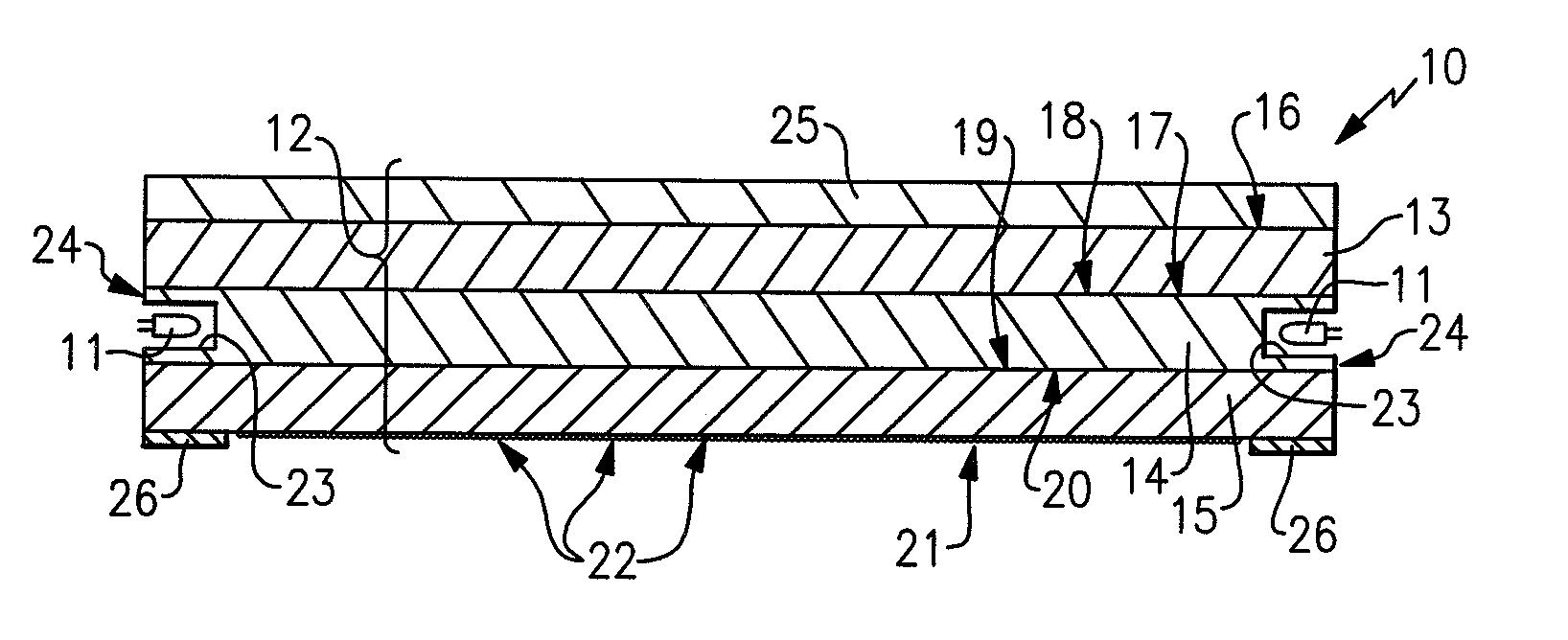
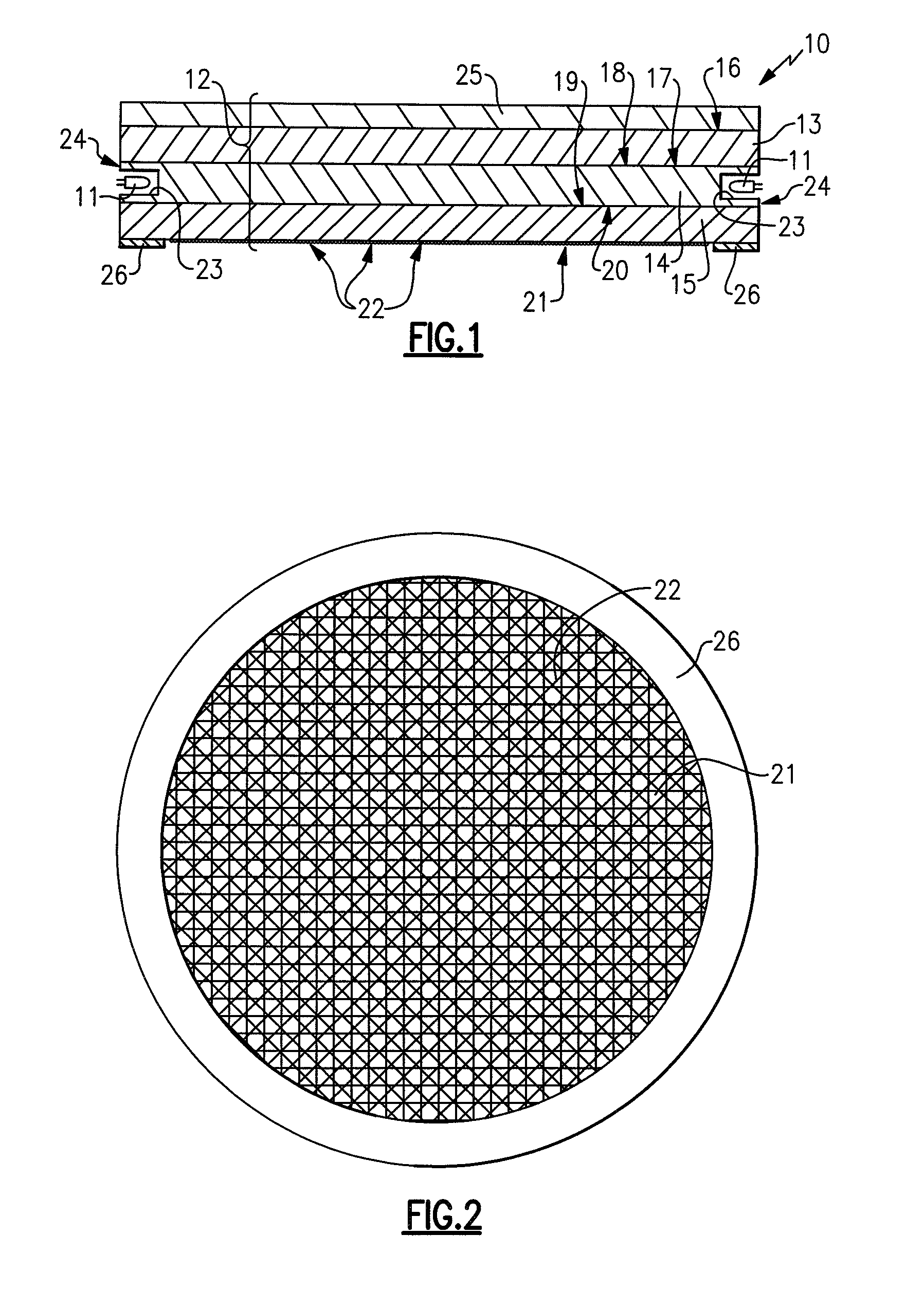
[0185]FIGS. 1 and 2 depict a lighting device in accordance with the present inventive subject matter. Referring to FIG. 1, there is shown a lighting device 10 comprising a plurality of LEDs 11 and a first optical device 12. The first optical device 12 is substantially circular disc-shaped, and comprises a first optical device structure 13, a second optical device structure 14 and a third optical device structure 15.

[0186]The first optical device structure 13 comprises a first structure first surface 16 and a first structure second surface 17. The second optical device structure 14 comprises a second structure first surface 18 and a second structure second surface 19. The third optical device structure 15 comprises a third structure first surface 20 and a third structure second surface 21.

[0187]The second optical device structure 13 has an edge region 24 positioned between the second structure first surface 18 and the second structure second surface 19, a plurality of cavities 23 bei...

second embodiment

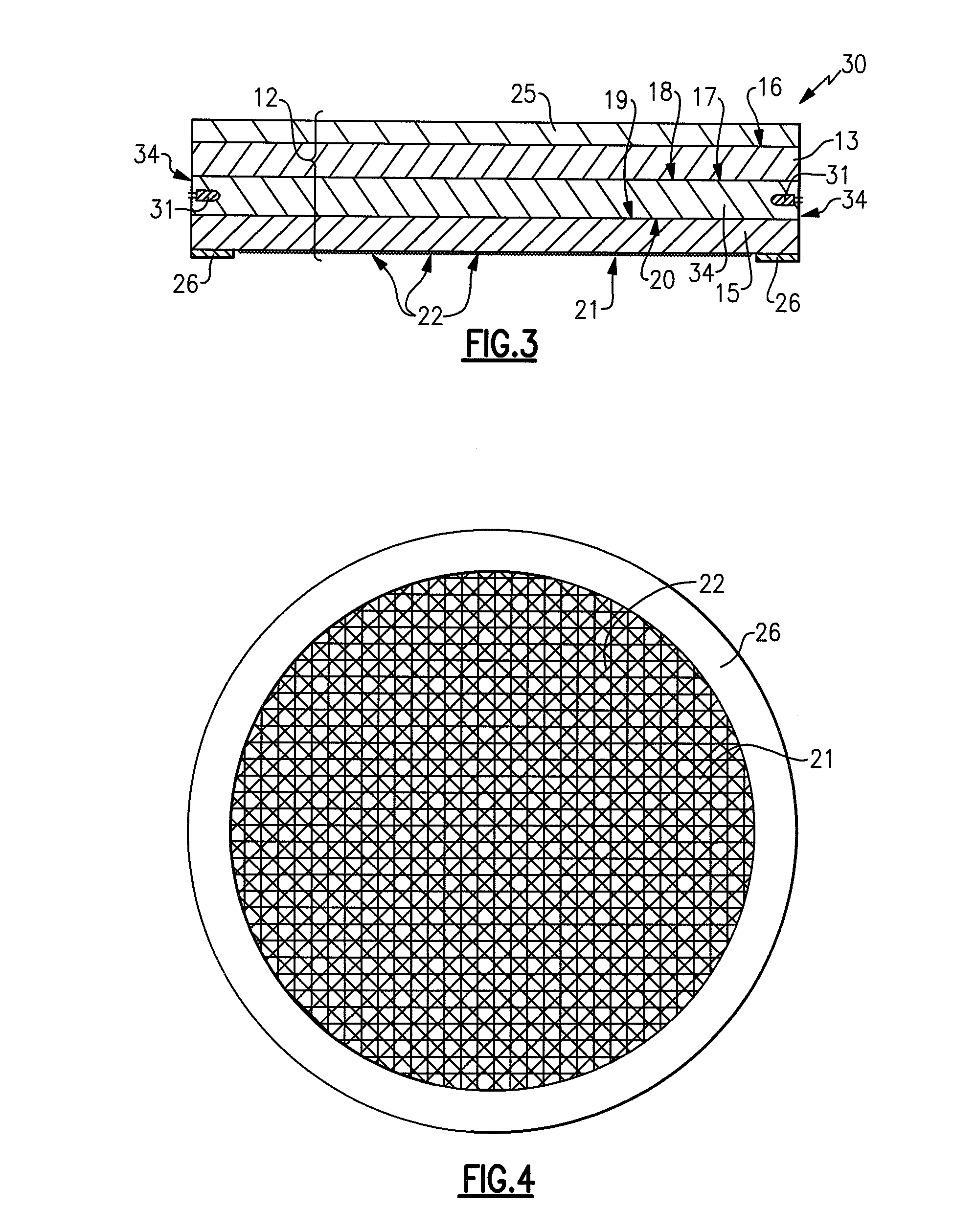
[0196]FIGS. 3 and 4 depict a lighting device in accordance with the present inventive subject matter. The lighting device 30 depicted in FIGS. 3 and 4 is identical to the lighting device depicted in FIGS. 1 and 2, except that in the lighting device depicted in FIGS. 3 and 4, the LEDs 31 are embedded in the second optical device structure 34 (rather than being positioned in cavities, as is the case with the LEDs 11 positioned in the cavities 23 depicted in FIG. 1).

third embodiment

[0197]FIGS. 5 and 6 depict a lighting device in accordance with the present inventive subject matter. The lighting device 50 depicted in FIGS. 5 and 6 is identical to the lighting device depicted in FIGS. 1 and 2, except that in the lighting device depicted in FIGS. 5 and 6, the first optical device 52 is substantially square disc-shaped (rather than circular disc-shaped, as is the first optical device 12 in the device depicted in FIGS. 1 and 2).

[0198]FIGS. 7 and 8 depict a fourth embodiment of a lighting device in accordance with the present inventive subject matter. Referring to FIGS. 7 and 8, there is shown a lighting device 70 which comprises a first optical device 71, a second optical device 72 and a third optical device 73. Each of the three optical devices (i.e., the first optical device 71, the second optical device 72 and the third optical device 73) is similar to the first optical device 12 of the first embodiment, except that (1) only the first optical device 71 has a ref...


PUM


Abstract

A lighting device, comprising at least one solid state light emitter and one (or more) optical device(s) which (each) comprises at least first, second and third optical structures, first and second surfaces of the second structure being in contact with a surface of the first structure and a surface of the third structure, respectively. The third structure has at least one optical feature. The light emitter is positioned, the optical feature is positioned, and the regions of the structures have indices of refraction, such that if the light emitter is illuminated, at least a portion of the emitted light will enter into the second optical device structure and exit from the optical feature on the third structure. Also, a method of lighting comprising illuminating a light emitter in such a device.

Description

CROSS-REFERENCE TO RELATED APPLICATIONS[0001]This application claims the benefit of U.S. Provisional Patent Application No. 60 / 858,558, filed Nov. 13, 2006, the entirety of which is incorporated herein by reference.FIELD OF THE INVENTION(S)[0002]The present inventive subject matter relates to lighting devices which include solid state light emitters. In some aspects, the present inventive subject matter relates to lighting devices which include LEDs and / or lumiphors.BACKGROUND OF THE INVENTION(S)[0003]A large proportion (some estimates are as high as twenty-five percent) of the electricity generated in the United States each year goes to lighting. Accordingly, there is an ongoing need to provide lighting which is more energy-efficient. It is well-known that incandescent light bulbs are very energy-inefficient light sources—about ninety percent of the electricity they consume is released as heat rather than light. Fluorescent light bulbs are more efficient than incandescent light bul...

Claims


Application Information

Patent Timeline
IPC IPC(8): F21V8/00F21K99/00
CPCF21K9/52F21Y2101/02G02B6/0011F21Y2113/00G02B6/0055G02B6/0073F21Y2105/00G02B6/0021F21K9/61F21Y2115/10
Inventor NEGLEY, GERALD H.
Owner IDEAL IND LIGHTING LLC
Why Eureka
Try Eureka