
Differential pitch hammerless connection with hydraulic driving mechanism

a technology of hydraulic driving mechanism and different pitch hammer, which is applied in the direction of hose connection, screw threaded joint, transportation and packaging, etc., can solve the problems of significant impact load required to make up the threaded connection, significant preload force may be required to maintain the face seal, and various types of physical injuries to personnel, including stress-related injuries

Inactive Publication Date: 2008-05-22
HALLIBURTON ENERGY SERVICES INC
View PDF14 Cites 25 Cited by
  • Summary
  • Abstract
  • Description
  • Claims
  • Application Information

AI Technical Summary

Benefits of technology

[0008]In one aspect, the present disclosure relates to a threaded connection assembly comprising a nut, a multiplier connected to the nut via a first threaded interface having a first number of threads per inch (first TPI), and a well servicing pipe coupling connected to the multiplier via a second threaded interface having a second number of threads per inch (second TPI). The first threaded interface and the second threaded interface may be at least partially formed simultaneously. In an embodiment, the first TPI is less than the second TPI. The threaded connection assembly may further comprise a negative equivalent TPI between the nut and the well servicing pipe coupling. In an embodiment, the nut connects to the well servicing pipe coupling via a non-threaded connection. The well servicing pipe coupling may comp

Problems solved by technology

A significant amount of preload force may be required to maintain the face seal when under pressure.
Hence, the impact load necessary to make up the threaded connection can be significant, requiring repeated blows of a sledge hammer that may weigh approximately 6 to 8 pounds, for example.
Such impact loading may lead to various types of physical injuries, including stress-related injuries, to the personnel who make up these connections, especially in extremely cold or extremely hot environments.

Method used


Image

  • Differential pitch hammerless connection with hydraulic driving mechanism
  • Differential pitch hammerless connection with hydraulic driving mechanism
  • Differential pitch hammerless connection with hydraulic driving mechanism

Examples


Embodiment Construction

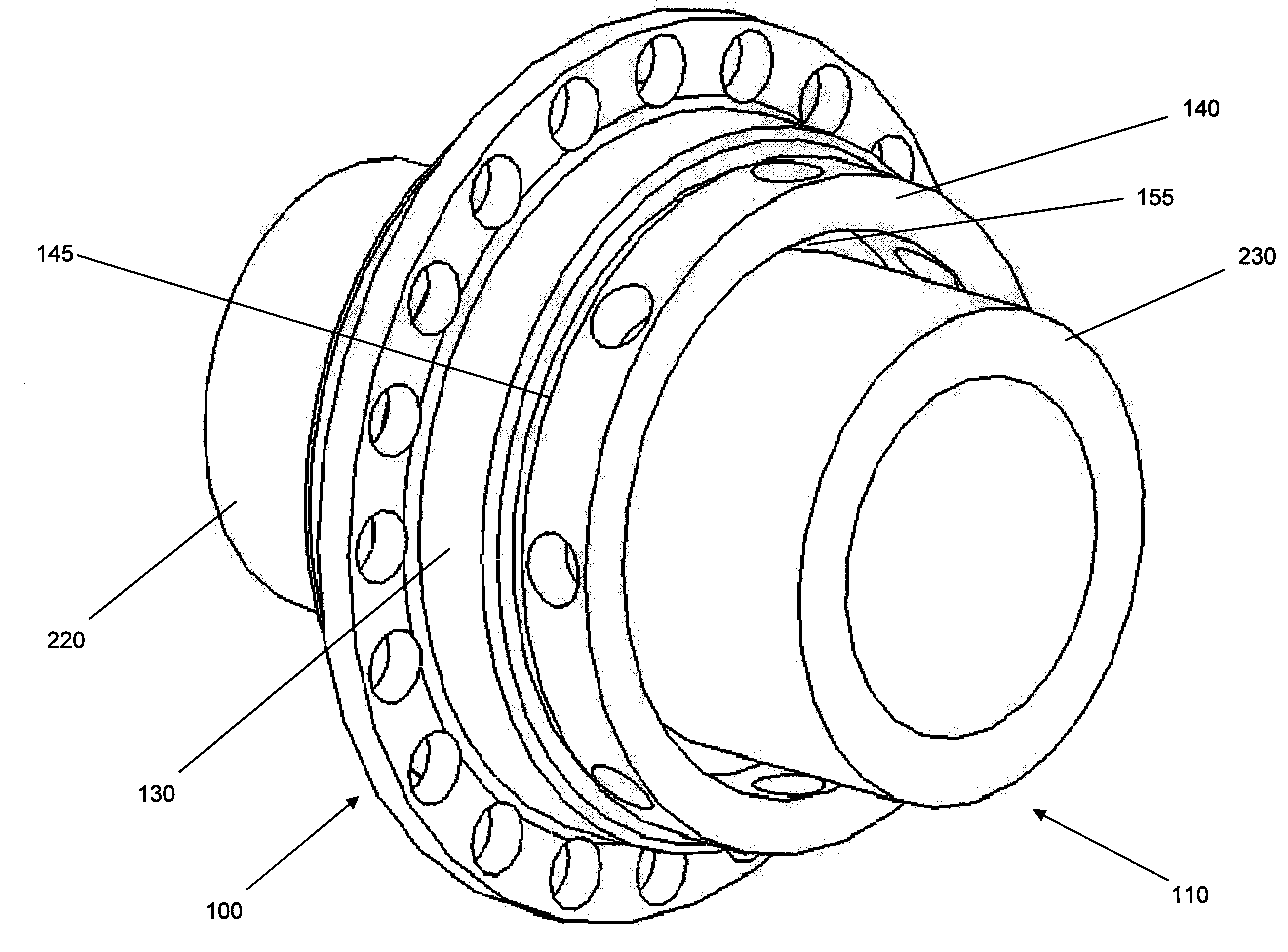
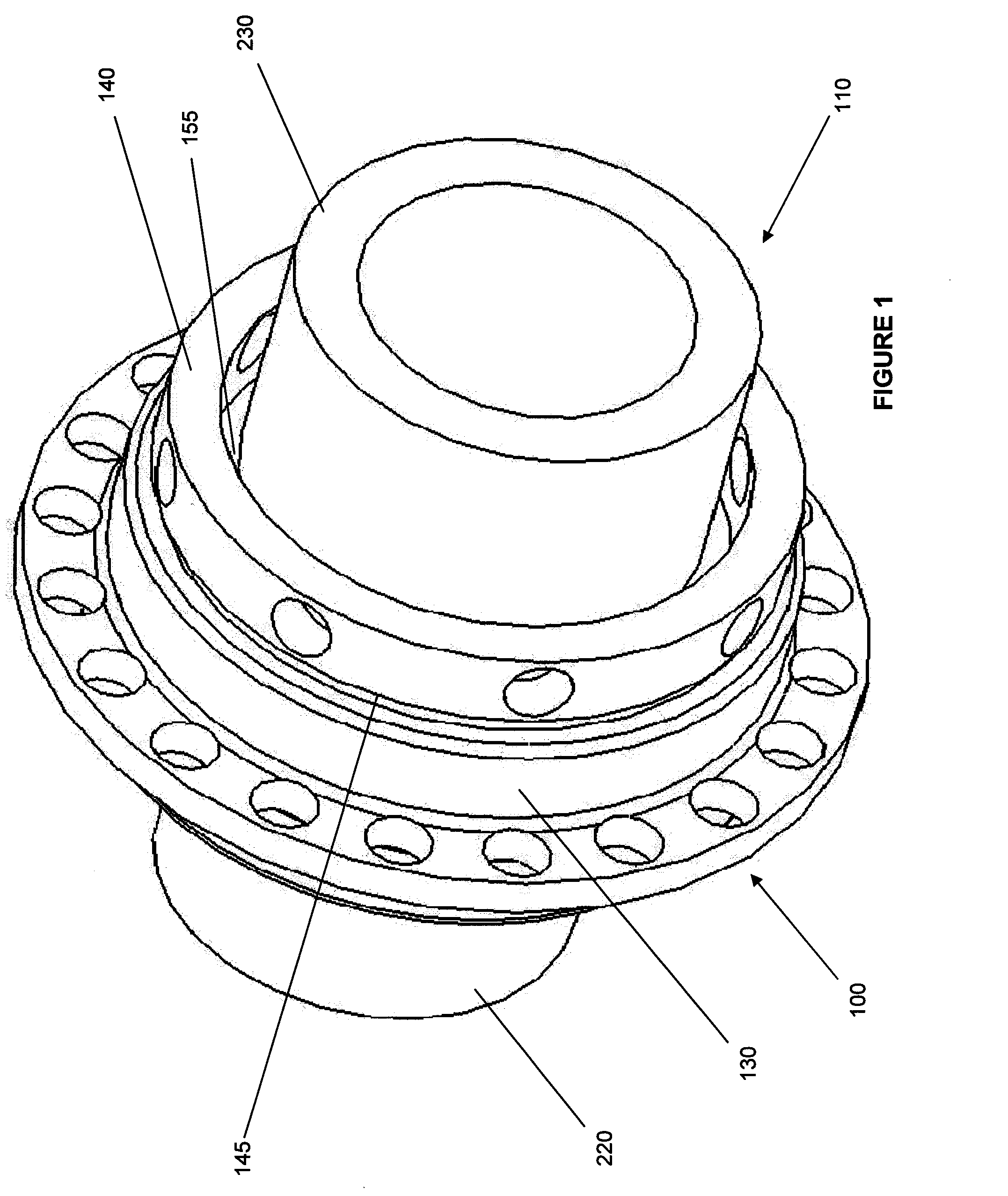
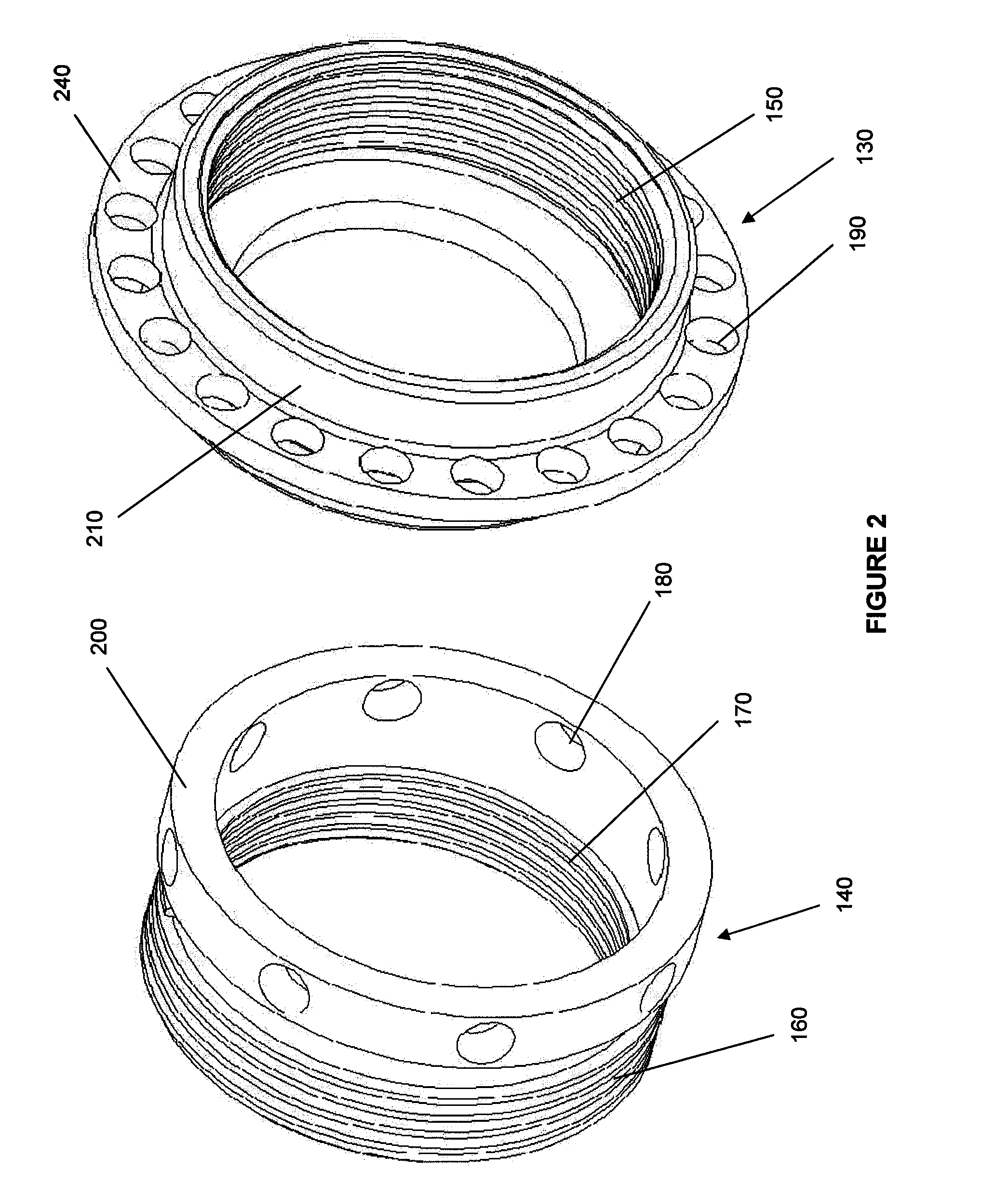
[0032]Various embodiments of threaded connectors for use in well servicing applications will now be described with reference to the accompanying drawings, wherein like reference numerals are used for like features throughout the several views. There are shown in the drawings, and herein will be described in detail, specific embodiments of threaded connectors operable to connect two pipe sections together without the application of an impact load, with the understanding that this disclosure is representative only and is not intended to limit the invention to those embodiments illustrated and described herein. The embodiments of the threaded connectors and the methods disclosed herein may be used in any type of well servicing application where it is desired to connect two pipe sections together. It is to be fully recognized that the different teachings of the embodiments disclosed herein may be employed separately or in any suitable combination to produce desired results.

[0033]FIG. 1 ...


PUM


Abstract

A threaded connection assembly comprises a nut, a multiplier connected to the nut via a first threaded interface having a first number of threads per inch and a well servicing pipe coupling connected to the multiplier via a second threaded interface having a second number of threads per inch. A method of forming a threaded connection for a well servicing application comprises forming a pipe coupling between two well servicing pipe sections and threading a connector to the pipe coupling to form a threaded connection without impact loading the connector. Another method for forming a threaded connection comprises disposing a first pipe section partially within a nut, threading a multiplier into the nut, threading the multiplier onto a second pipe section, and leveraging the multiplier against the nut, or vice versa.

Description

CROSS-REFERENCE TO RELATED APPLICATIONS[0001]The present application is related to U.S. patent application Ser. No. 11 / 292,981 filed Dec. 2, 2005 and entitled “Threaded Connector for Well Servicing Applications,” which is hereby incorporated by reference herein in its entirety.STATEMENT REGARDING FEDERALLY SPONSORED RESEARCH OR DEVELOPMENT[0002]Not applicable.REFERENCE TO A MICROFICHE APPENDIX[0003]Not applicable.FIELD OF THE INVENTION[0004]The present invention relates generally to threaded connectors comprising differential thread pitches, and methods of making up a pipe connection via such threaded connectors. More particularly, the present invention relates to threaded connectors for well servicing applications and methods of connecting two pipe sections together by leveraging one component of a threaded connector against another.BACKGROUND[0005]Threaded connectors, such as a union comprising an internally threaded nut, for example, may be used to provide a preloaded threaded co...

Claims


Application Information

Patent Timeline
IPC IPC(8): F16L25/04F17D1/00
CPCF16L15/009F16L19/0225F16L15/08Y10T137/4857
Inventor BULL, BRADCASE, LEONARDDEAN, TODDBLANCO, IVAN
Owner HALLIBURTON ENERGY SERVICES INC
Learn More