Foldable Mat

a mat and folding technology, applied in the field of mats, can solve problems such as inability to be easily configured

Inactive Publication Date: 2008-05-22
BIENKIEWICZ LIDIA
View PDF3 Cites 44 Cited by
  • Summary
  • Abstract
  • Description
  • Claims
  • Application Information

AI Technical Summary

Benefits of technology

[0027]The mat may have retaining means for holding together the panels when fully stacked, for ease with transportation or stowage in a compact form. Any suitable type of retaining means may be used. Preferably, the retaining means comprises a retaining flap extending from one of the panels and a fastener. The retaining flap may be extendible around the stacked panels and a free end of the flap may be detachably connected to another region of the flap by way of the fastener. Preferably, the retaining flap extends from an end panel of the mat. Any suitable type of fastener may be used, including a hook and loop type fastener, press studs or clips. One portion of the fastener may be located at one end of the retaining flap and the other portion of the fastener may be located at the opposing end of the retaining flap.

Problems solved by technology

Although some of those mats can adopt a more compact form for ease with transport or stowage, such mats typically have the disadvantage in that they can not be readily configured such that, say, one region of the mat is elevated relative to another region of the mat.

Method used


Image

  • Foldable Mat
  • Foldable Mat
  • Foldable Mat

Examples


Embodiment Construction

[0036]In the figures, like reference numerals refer to like features.

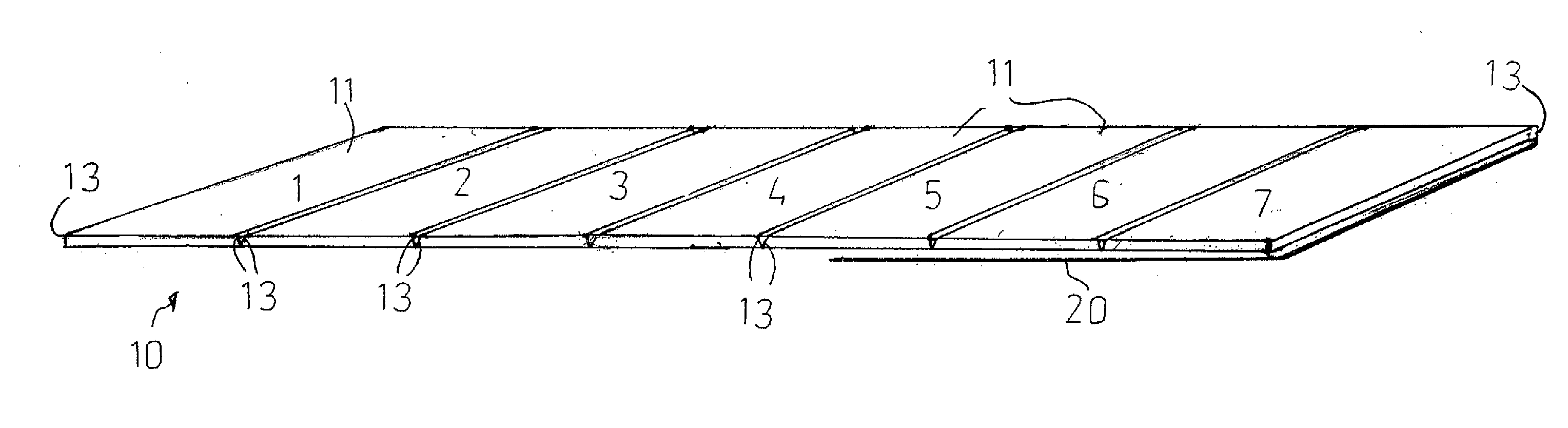
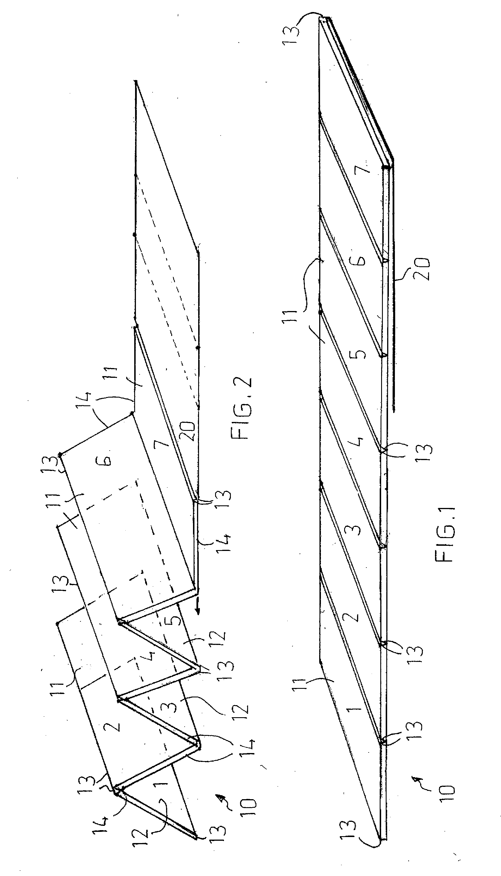
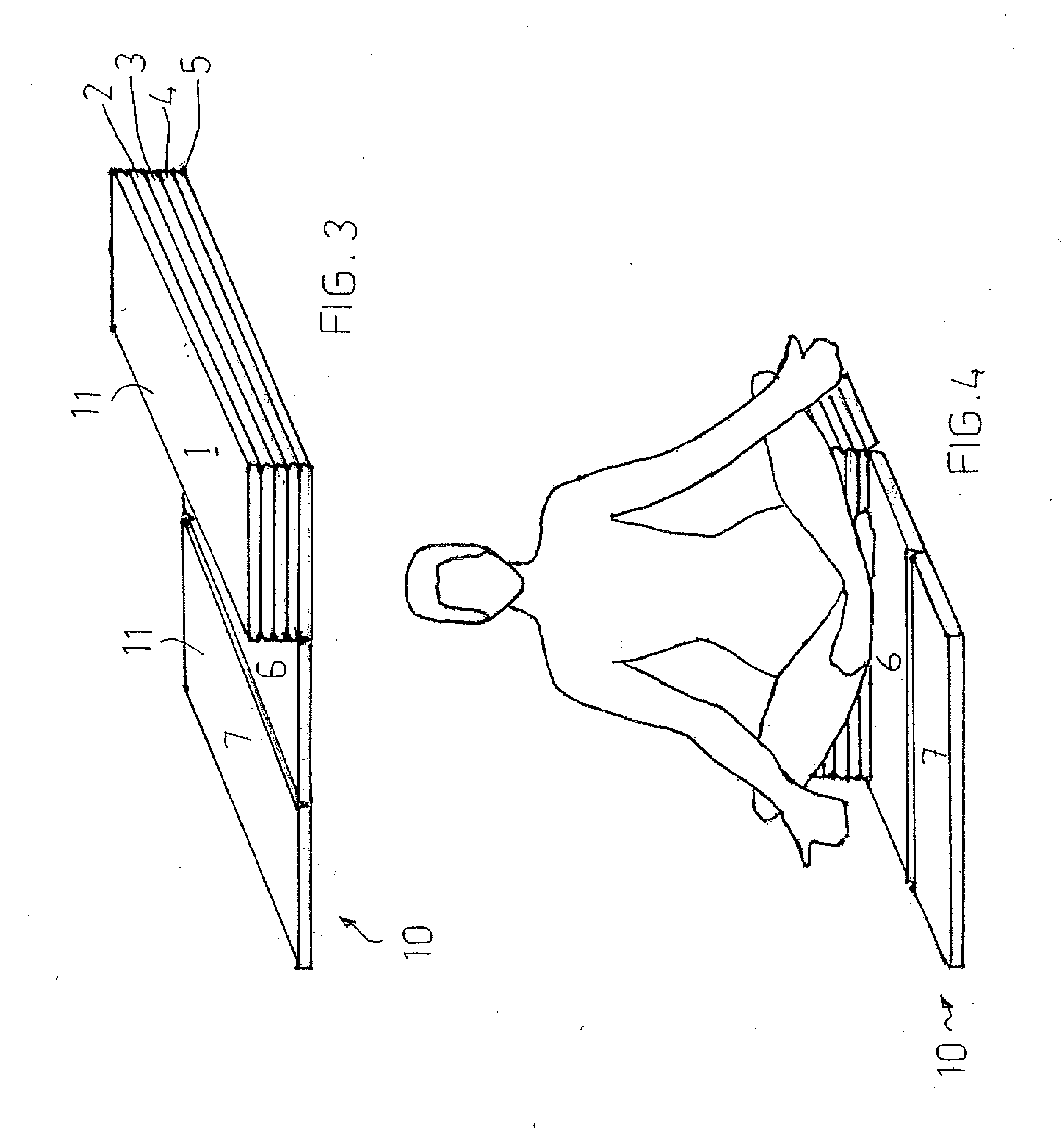
[0037]The figures show a foldable elongate mat 10 for use on a floor or other support surface. The mat 1 comprises seven cushioning panels 1-7 hingedly connected to one another in a concertina-like arrangement, retaining means 20-22 and a carry handle 8 (see FIGS. 5 and 6).

[0038]Each panel 1-7 has a flexible covering (not labeled) and a cushioning foam rubber insert (not shown). As seen in FIG. 1, each panel 1-7 is rectangular and has a top surface 11, a bottom surface 12, a pair of ends 13 and a pair of sides 14 (only partly labeled). The ends 13 of the panels 1-7 are hingedly connected to one another and enable the panels 1-7 to be moved between a folded stacked position (as seen in FIGS. 3-6) and an unfolded position (as seen in FIG. 1). In the folded stacked position the respective top or bottom surfaces 11, 12 of any two adjacent panels 1-7 extend co-planarly and are in direct contact with one another. In the ...


PUM


Abstract

A foldable elongate mat (10) comprising seven cushioning panels (1-7) hingedly connected to one another and moveable relative to one another between a folded stacked position and an unfolded position. The mat (10) further comprises a retaining flap (20) and a carrying handle. Each panel (1-7) has a flexible covering and a cushioning foam rubber insert. The coverings are provided by a fabric sheet, the inserts are sewn into the sheet, ends (13) of the panels (1-7) correspond with seams extending across the mat (10) between adjacent inserts, and the hinging action is largely provided by fold lines at the seams and adjacent regions of the sheet extending alongside the inserts. The mat (10) may be configured for many different uses, and for ready transportation and stowage in a compact form.

Description

CROSS-REFERENCE TO PRIOR APPLICATIONS[0001]This application claims priority from Australian provisional patent application number 2006906416, filed Nov. 16, 2006, which is incorporated herein by reference.U.S. GOVERNMENT SUPPORT [0002]Not ApplicableBACKGROUND [0003]1. Area of the Art[0004]The present invention is in the art of mats such as those used in exercise and is particularly directed to a foldable configuration.[0005]2. Description of the Background of the Invention[0006]Elongate mats for use on floors and for cushioning other surfaces are available in a range of shapes and sizes. Although some of those mats can adopt a more compact form for ease with transport or stowage, such mats typically have the disadvantage in that they can not be readily configured such that, say, one region of the mat is elevated relative to another region of the mat. A user may wish to use such an elevated region as a head or foot support, or as a seat.[0007]The present inventor has now developed a ...

Claims


Application Information

Patent Timeline
Patent Type & Authority Applications(United States)
IPC IPC(8): A47G9/00
CPCA47C27/001A63B21/1473A47G9/062A63B21/4037
Inventor BIENKIEWICZ, LIDIA
Owner BIENKIEWICZ LIDIA
Why Eureka
Try Eureka