Hermetically sealed electromechanical relay

a technology of electromechanical relays and hermetically sealed relays, which is applied in the direction of relays, non-polarised relays, contacts, etc., can solve the problems of contact welding of high-current relays, short circuiting of relay terminals, and epoxy potting compounds having a lower temperature rating

Active Publication Date: 2008-05-29
TYCO ELECTRONICS LOGISTICS AG (CH)
View PDF20 Cites 52 Cited by
  • Summary
  • Abstract
  • Description
  • Claims
  • Application Information

AI Technical Summary

Benefits of technology

[0005]In one aspect, an electromechanical relay includes an armature and an inner core at least partially surrounding at least a portion of the armature. The armature is slidably movable relative to the inner core. A coil at least partially surrounds at least a portion of the inner core. The relay also includes a stationary contact held in a ceramic header and a movable contact connected to the armature via a shaft. The movable contact is movable between an open position wherein the movable contact does not engage the stationary contact and a closed position wherein the movable contact engages the stationary contact. The relay also includes a housing having an open end and a chamber. The chamber contains the armature, the inner core, the coil, the movable contact, and at least a portion of the stationary contact. The housing forms a portion of a magnetic circuit of the relay. The ceramic header is circumferentially welded to the housing adjacent the open end such that the chamber of the housing is hermetically sealed.
[0006]In another aspect, an electromechanical relay includes an armature and an inner core at least partially surrounding at least a portion of the armature. The armature is slidably movable relative to the inner core. The relay also includes a coil at least partially surrounding at least a portion of the inner core, a stationary contact, and a movable contact connected to the armature via a shaft. The movable contact is movable between an open position wherein the movable contact does not engage the stationary contact and a closed position wherein the movable contact engages the stationary contact. The relay also includes a housing having a chamber. The chamber contains the armature, the inner core, the coil, the movable contact, and at least a portion of the stationary contact. The relay also includes a permanent magnet held within the chamber of the housing. The movable contact is magnetically latchable in the open and closed positions by the permanent magnet. The movable contact is unlatched from the open and closed positions and latched in the open and closed positions by application of power to the coil.

Problems solved by technology

High voltage, high current relays may suffer from contact welding and short circuiting of the relay terminals through vapor deposition of metal across the relay housing.
These problems are caused by arcing between the moving contact and the stationary contacts, for example during hot switching operations.
However, the epoxy potting compound may have a lower temperature rating than desired for some relay applications, which may compromise the hermetic seal above some temperatures.
Moreover, some epoxy potting compounds may be porous to some gases, for example hydrogen, which may compromise the ability of the epoxy potting compound to hold a complete vacuum and / or contain some inert and / or insulating gases.

Method used


Image

  • Hermetically sealed electromechanical relay
  • Hermetically sealed electromechanical relay
  • Hermetically sealed electromechanical relay

Examples


Embodiment Construction

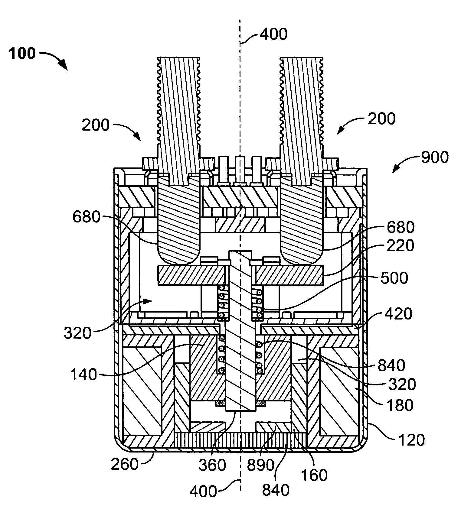
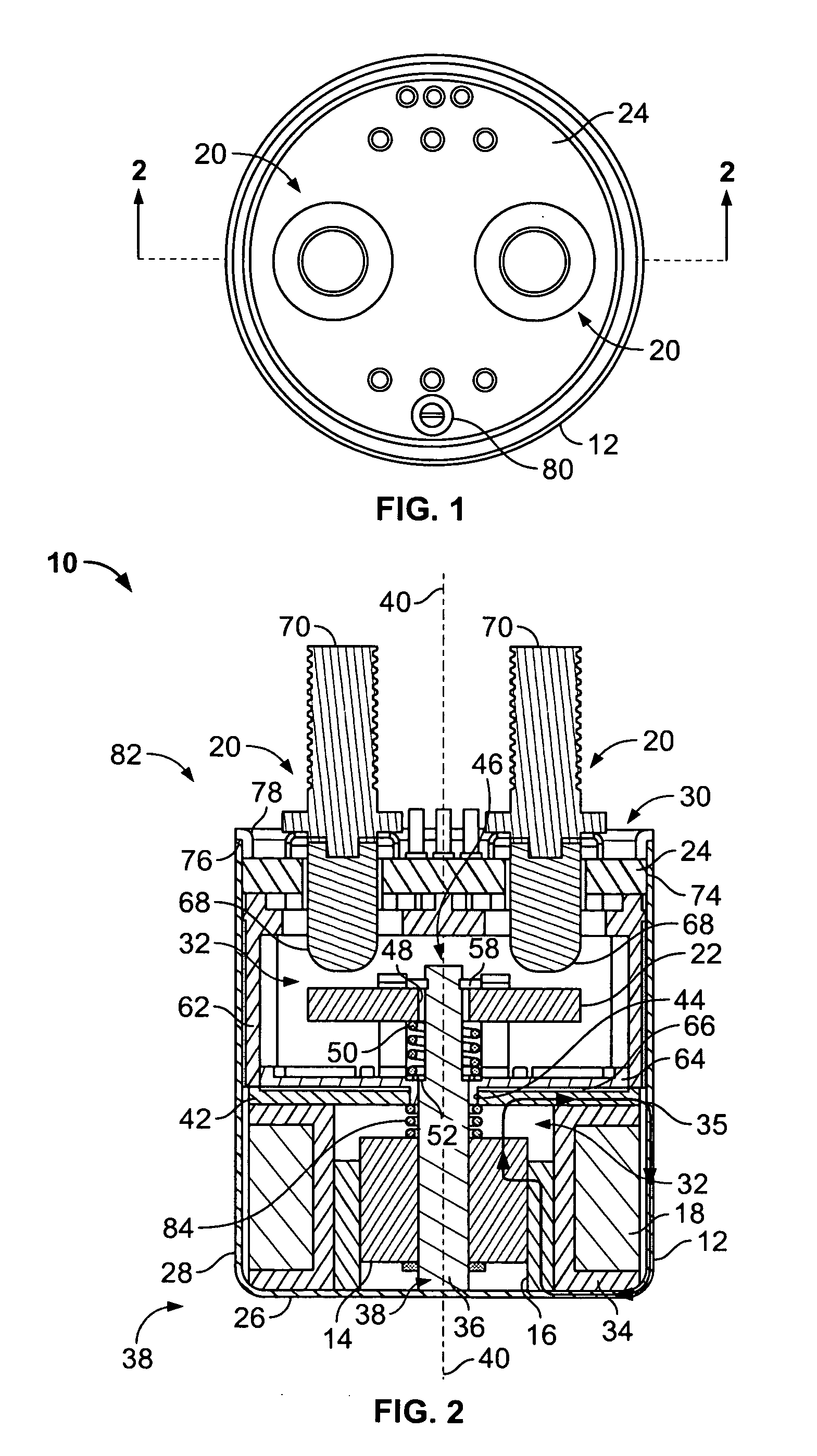
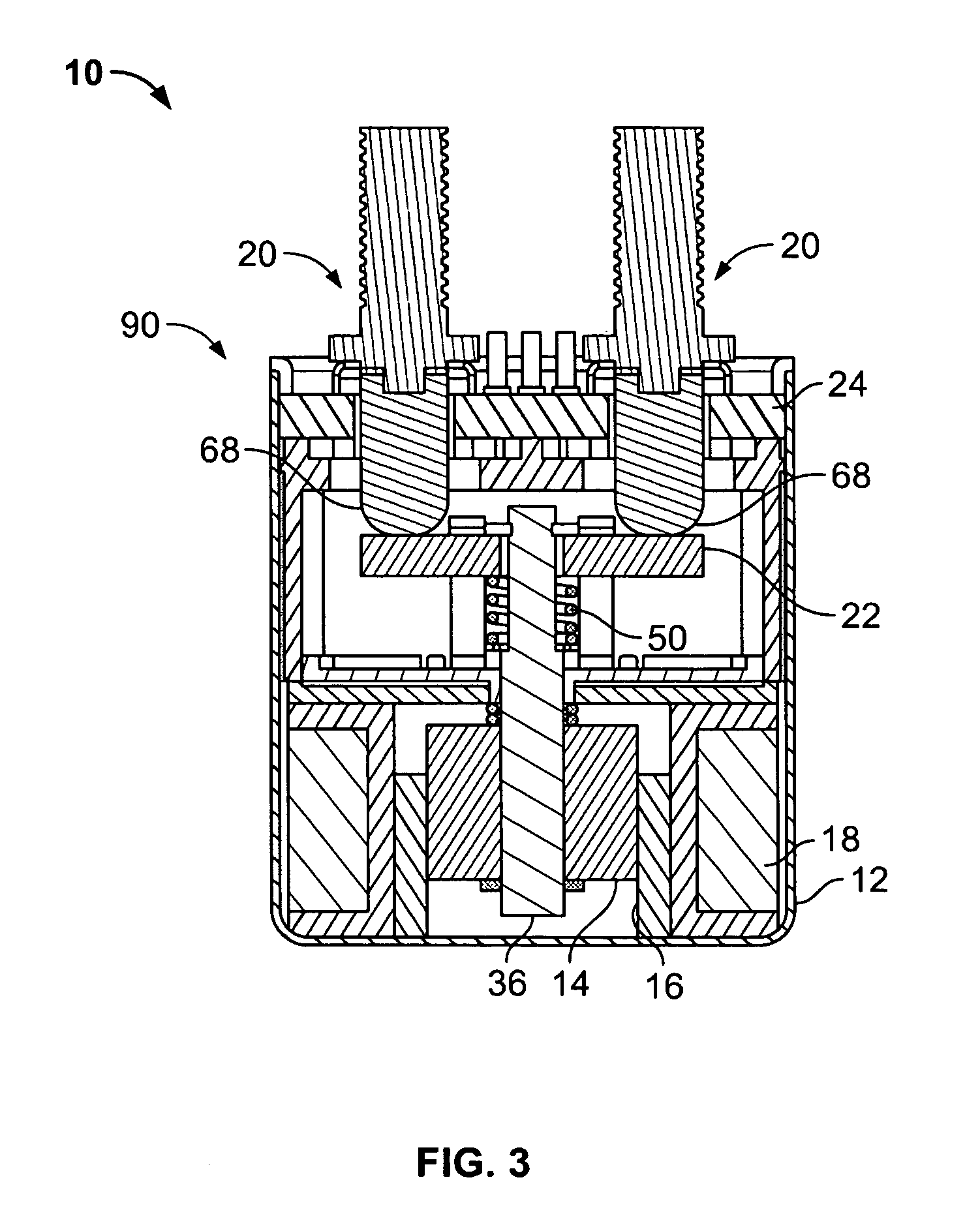
[0013]Referring now to FIGS. 1 and 2, an electromechanical relay 10 formed in accordance with an embodiment of the present invention generally includes a housing 12, an armature 14, an inner core 16, a coil 18, a pair of stationary contact assemblies 20, one or more movable contacts 22, and a ceramic header 24. The housing 12 includes a bottom wall 26, a side wall 28 extending from the bottom wall 26, and an open end 30. The side and bottom walls 28, 26, respectively, define a chamber 32 extending between the bottom wall 26 and the open end 30. The coil 18 is wound on a bobbin 34 held within the chamber 32 adjacent the bottom wall 26 of the housing 12. The coil 18 surrounds the inner core 16, which is fabricated from a ferromagnetic material and is also held within the chamber 32 adjacent the bottom wall 26 of the housing 12. The relay 10 may optionally include an internal coil control circuit (not shown) configured to regulate power dissipated by the coil 18 when energized.

[0014]Th...


PUM


Abstract

An electromechanical relay includes an armature and an inner core at least partially surrounding at least a portion of the armature. The armature is slidably movable relative to the inner core. A coil at least partially surrounding at least a portion of the inner core. The relay also includes a stationary contact held in a ceramic header and a movable contact connected to the armature via a shaft. The movable contact is movable between an open position wherein the movable contact does not engage the stationary contact and a closed position wherein the movable contact engages the stationary contact. The relay also includes a housing having an open end and a chamber. The chamber contains the armature, the inner core, the coil, the movable contact, and at least a portion of the stationary contact. The housing forms a portion of a magnetic circuit of the relay. The ceramic header is circumferentially welded to the housing adjacent the open end such that the chamber of the housing is hermetically sealed.

Description

BACKGROUND OF THE INVENTION[0001]The invention relates generally to electromechanical relays and, more particularly, to hermetically sealed electromechanical relays.[0002]Hermetically sealed electromagnetic relays are sometimes used in explosive environments and / or for switching relatively high electrical currents and / or voltages. Hermetically sealed relays typically have stationary and movable contacts, and an actuating mechanism supported within a hermetically sealed chamber. High voltage, high current relays may suffer from contact welding and short circuiting of the relay terminals through vapor deposition of metal across the relay housing. These problems are caused by arcing between the moving contact and the stationary contacts, for example during hot switching operations. To suppress arcing, the relay chamber is evacuated and sealed so that the fixed and movable contacts coact in a complete or partial vacuum environment. Alternatively, the evacuated chamber is backfilled with...

Claims


Application Information

Patent Timeline
Patent Type & Authority Applications(United States)
IPC IPC(8): H01H1/66H01H51/01
CPCH01H51/2209H01H2050/025H01H51/29H01H51/27H01H50/023
Inventor BUSH, BERNARD VICTORPRIEST, MARCUS
Owner TYCO ELECTRONICS LOGISTICS AG (CH)
Why Eureka
Try Eureka