Battery busing scheme

a battery and busing technology, applied in the field of multi-cell batteries, to achieve the effect of ensuring safe passage of large amounts of current and more efficient battery power

Active Publication Date: 2008-05-29
SECURAPLANE TECH
View PDF12 Cites 168 Cited by
  • Summary
  • Abstract
  • Description
  • Claims
  • Application Information

AI Technical Summary

Benefits of technology

The patent text discusses the development of thin plate batteries and the need for efficient battery power in industry applications. This has led to the creation of new busing concepts and circuit protection. The battery packs must meet the high power demands and be capable of passing large amounts of current safely from the thin plate battery assemblies. The thin plate batteries allow for minimal space usage for the applications enclosure with all the components required for the battery technology.

Problems solved by technology

The technical problem of this patent text is not specified and requires further analysis and interpretation.

Method used


Image

  • Battery busing scheme
  • Battery busing scheme
  • Battery busing scheme

Examples


Embodiment Construction

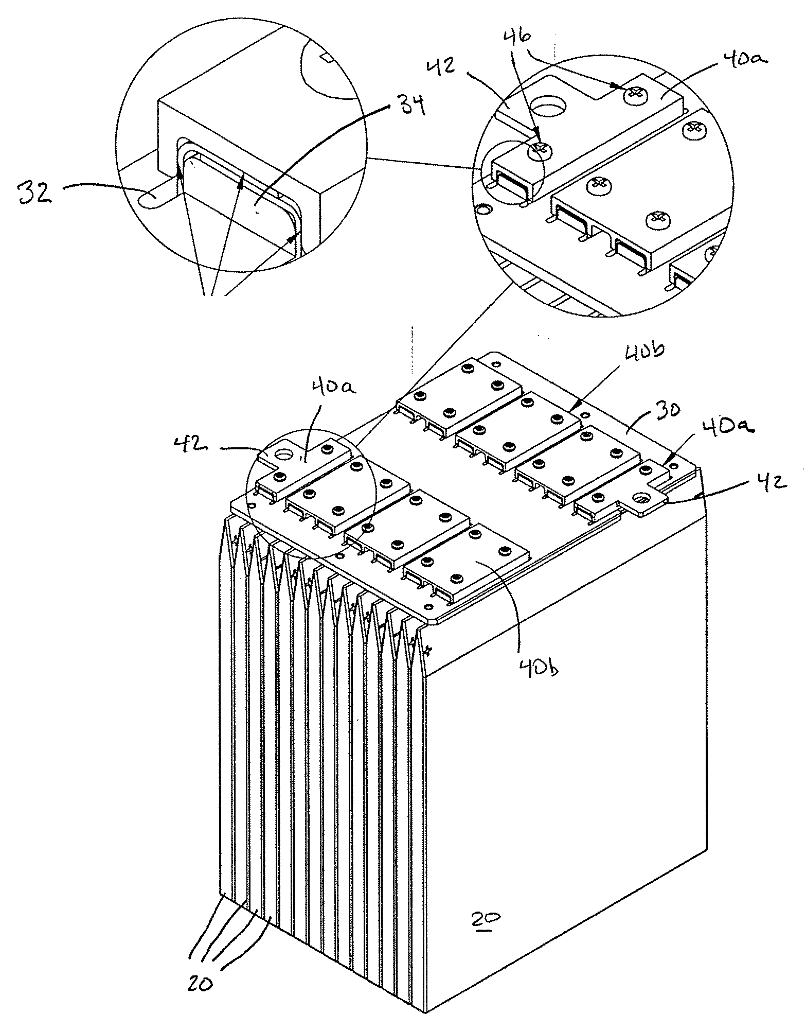
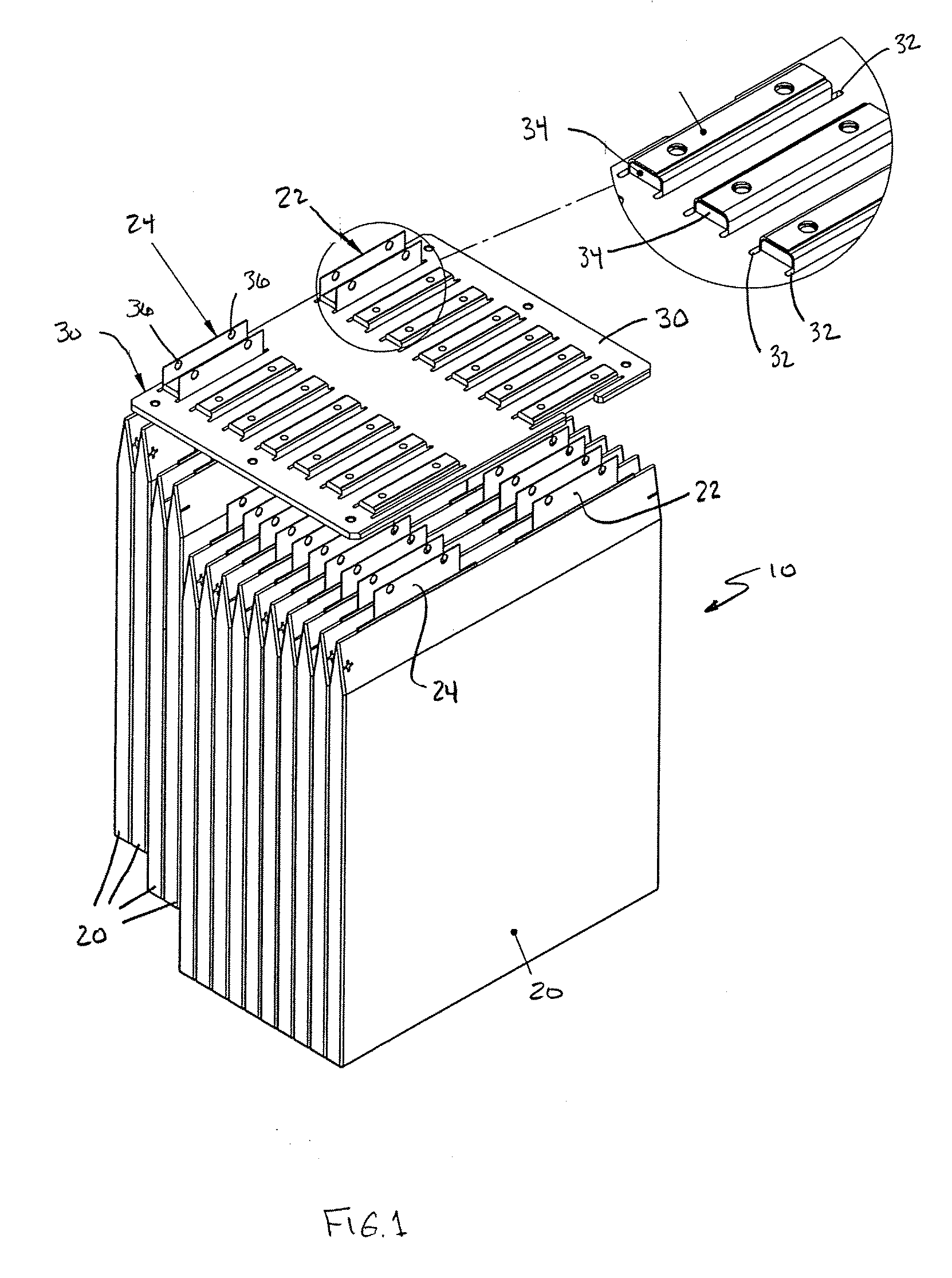
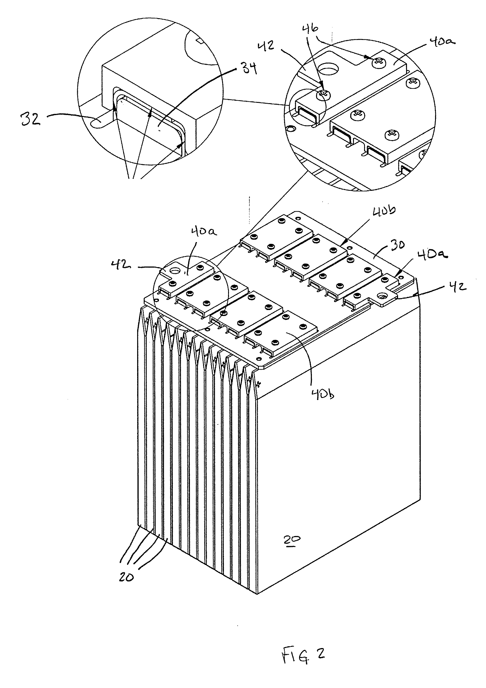
[0017]Referring to FIG. 1, a battery 10 of the described embodiment is made up of a set of thin plate cells 20 arranged next to each other. Each thin plate cell 20 is rectangularly shaped, has a thin profile and includes two terminals plates, a cathode (or negative) terminal plate 22 and an anode (or positive) terminal plate 24, both extending up from the top of the cell. The terminal plates are thin metal tabs made of copper and electroplated plated with tin to prevent corrosion. Cells 20 are all arranged so that all of their terminal plates extend in the same direction, which in FIG. 1 is upward. In this example, there are 14 thin film cells arranged within the battery so that their polarity alternates in pairs. In other words, the first two cells have their anodes on the left, the next two cells have their cathodes on the left, and that pattern repeats for the rest of the cells in the battery. As will become apparent shortly, when the electrical interconnections are described, th...


PUM


Abstract

A battery including: a plurality of battery cells arranged side-by-side, each battery cell including a terminal tab for delivering power from the cell; a bus plate made of an electrically non-conductive material, the bus plate also having an array of holes formed therein, the array of holes defining a plurality of hole pairs, wherein the terminal tab from each cell of the plurality of cells extends through a corresponding different hole in the array of holes, wherein for each hole pair of the plurality of hole pairs, the terminal tabs extending through that hole pair are folded one over the other to produce overlapping tabs for that hole pair; and a plurality of clamps each of which clamps together the overlapping tabs of a corresponding different hole pair.

Description


Claims


Application Information

Patent Timeline
Owner SECURAPLANE TECH
Why Eureka
Try Eureka