Voice Coil Motor Control Device and Method of Driving the Same, Image Pickup Device

a voice coil motor and control device technology, applied in the direction of instruments, television systems, focusing aids, etc., can solve the problems of shortening the focusing time, achieve the effect of suitable lenses, and improving the hysteresis characteristics of the voice coil motor

Inactive Publication Date: 2008-06-05
MITSUBISHI ELECTRIC CORP
View PDF10 Cites 33 Cited by
  • Summary
  • Abstract
  • Description
  • Claims
  • Application Information

AI Technical Summary

Benefits of technology

[0008]The present invention has been made to solve the problems such as described above, and has an object to provide a control device capable of i...

Problems solved by technology

Further, the voice coil motor control device does not detect an evaluation v...

Method used


Image

  • Voice Coil Motor Control Device and Method of Driving the Same, Image Pickup Device
  • Voice Coil Motor Control Device and Method of Driving the Same, Image Pickup Device
  • Voice Coil Motor Control Device and Method of Driving the Same, Image Pickup Device

Examples


first preferred embodiment

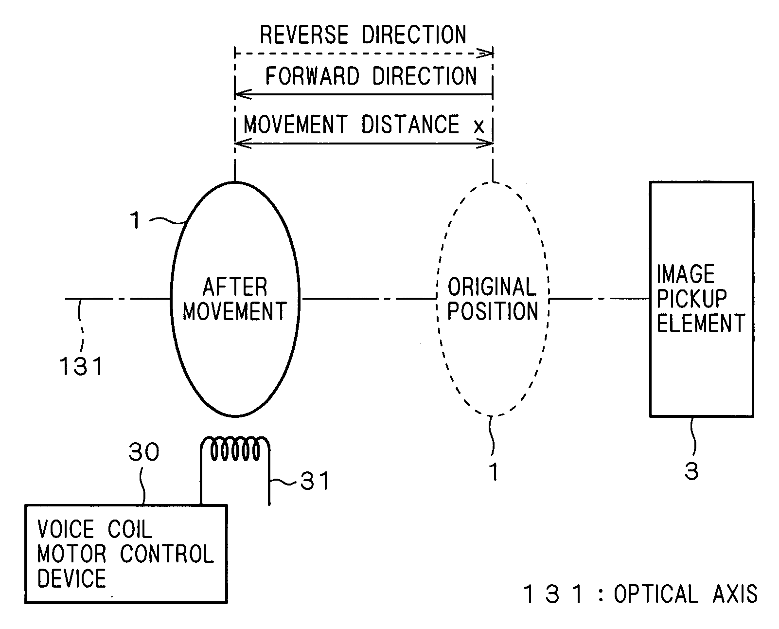
[0034]FIG. 1 is a block diagram of a focus control part in an image pickup device using a voice coil motor control device according to a first preferred embodiment of the present invention. The focus control part includes a lens 1 on an optical axis 131, an image pickup element 3, and a voice coil motor 31. The voice coil motor 31 is connected to a voice coil motor control device 31, and moves the lens 1 in the direction of the optical axis 131. The lens 1 moves away from the image pickup element 3 in a forward direction or moves closer to the image pickup element 3 in a reverse direction, with a movement distance x from the original position. The lens 1 is at the original position with respect to the image pickup element 3 when an infinite distance is focused, or when pan focus is attained.

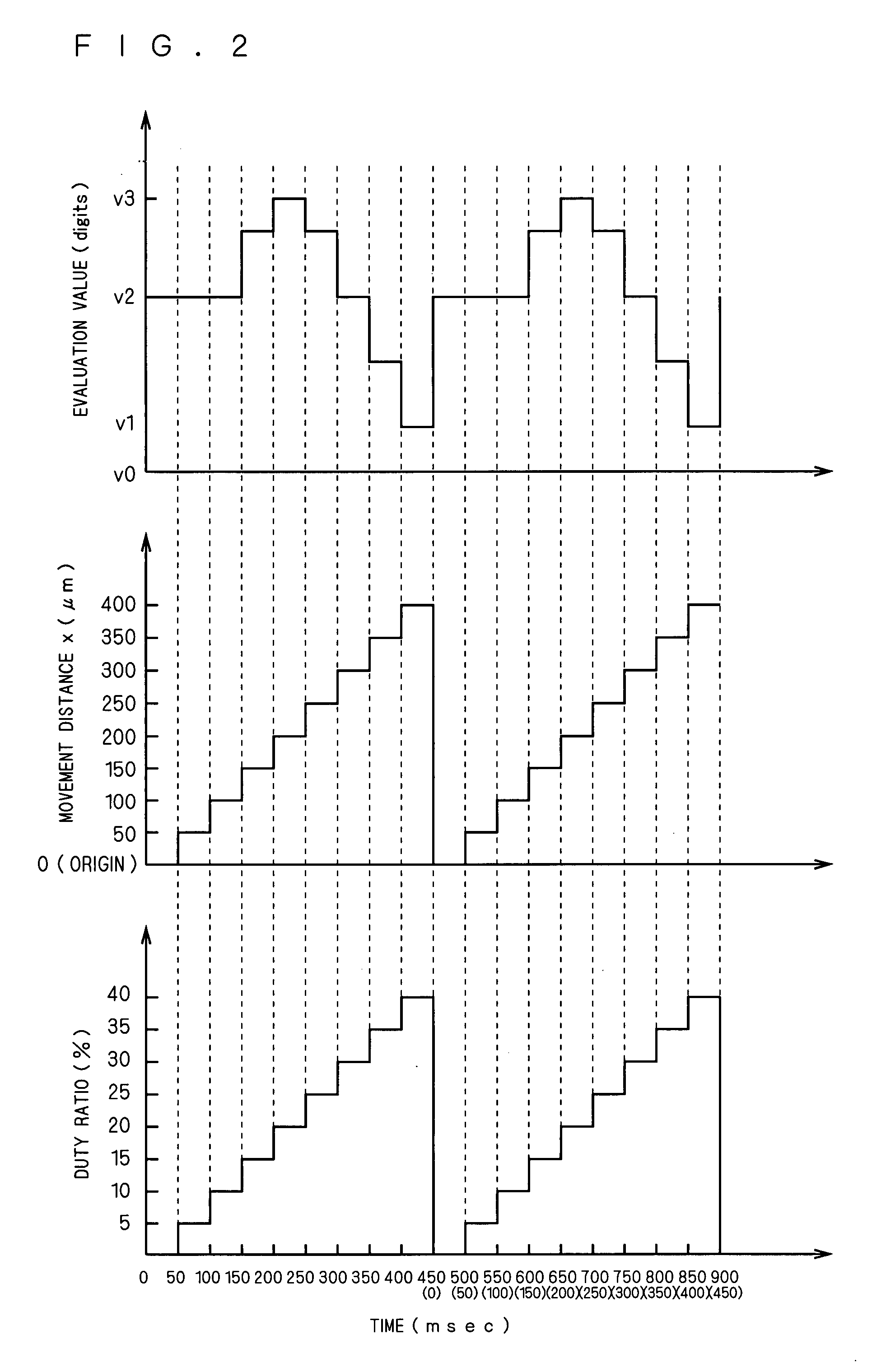
[0035]How to drive the voice coil motor 31 is explained by taking typical pulse width modulation drive as an example. The voice coil motor control device according to the invention may perform ot...

second preferred embodiment

[0071]FIG. 15 illustrates the structure of an image pickup device using the voice coil control device 30 described in the first preferred embodiment. The image pickup device shown in FIG. 15 has an autofocus feature, and includes the lens 1, an aperture 2, the image pickup element 3, an AFETG part 10, a DSP part 20, the voice coil motor control device 30, the voice coil motor 31, and external equipment 40.

[0072]The image pickup element 3 performs photoelectric conversion on incident light from a subject that has passed through the lens 1 and the aperture 2, and outputs the light as an image pickup signal 4. The image pickup signal output from the image pickup element 3 is converted to a RAW signal 118 which is a digital signal at the AFETG part 10. The AFETG part 10 includes a CDS part 11, an AGC part 12, an A / D part 13, a TG part 14, and an I / F part 15.

[0073]The CDS part 11 performs a CDS (Correlated Double Sampling) process on the image pickup signal 4 obtained by the image pickup...

third preferred embodiment

[0093]This embodiment is directed to control of the voice coil motor control device 30 according to the invention in an image pickup device in different orientations. FIGS. 22 to 24 are schematic diagrams of the image pickup device using the voice coil motor control device 30 in different orientations. In an image pickup device 72 shown in FIG. 22, a direction indicated by an arrow 70 denotes a forward direction of movement for the lens 1 driven by the voice coil motor 31. On the other hand, gravity acts on the image pickup device 72 in a direction indicated by an arrow 71. In short, the arrow 71 of gravity and the arrow 70 of movement direction of the lens 1 act in opposite directions, which means that the image pickup device 72 is arranged in an upward orientation. The voice coil motor 31 is controlled by the voice coil motor control device 30 according to the invention.

[0094]In an image pickup device 73 shown in FIG. 23, a direction indicated by the arrow 70 denotes a forward dir...


PUM


Abstract

The present invention provides a control device capable of improving hysteresis characteristics of a voice coil motor (31) and attaining a suitable lens position without complicating the structure of the control device. As solving means of the invention, a voice coil motor control device (30) includes a driving current control part (34) that controls a driving current supplied to the voice coil motor (31) in accordance with a driving pulse subjected to pulse width modulation, and a driving pulse control part (32) that divides a drive period of the voice coil motor (31) into a movement period and a holding period, and controls the driving pulse by changing the duty ratio of the driving pulse during the movement period in accordance with a duty setting value and fixing the duty ratio of the driving pulse during the holding period to the duty setting value.

Description

TECHNICAL FIELD[0001]The present invention relates to devices for controlling an optical length and the like between an optical component and an image pickup element, and more specifically to a control device using a voice coil motor.BACKGROUND ART[0002]Conventional image pickup devices use a stepping motor, a voice coil motor and the like for driving a focus lens, and include a control device for controlling them. Upon driving the focus lens by the stepping motor and the like, the control device exhibits hysteresis characteristics in that the position of the focus lens varies with drive directions. In a patent document 1, therefore, focus suffering from hysteresis characteristics is corrected by driving a focus lens in a U-turn such that a drive direction in which a maximum focus evaluation value has been detected coincides with a drive direction for moving the focus lens to a focus position, and detecting a maxim focus evaluation value again. This prevents a control device from be...

Claims


Application Information

Patent Timeline
IPC IPC(8): G02B15/14H02P7/29H02P7/285G02B7/08G02B7/09H02P25/06G02B7/28G02B7/36G03B13/36
CPCH02P25/028H04N5/23212H04N5/2254H02P25/034G02B7/09G02B7/36G03B13/36
Inventor ISHIDA, KOZOMICHIMORI, ATSUSHIKOMORI, NORIYUKIKUNISHIO, HIDEKISUGIURA, HIROAKIITOW, TAKASHIKUNO, TETSUYA
Owner MITSUBISHI ELECTRIC CORP
Why Eureka
Try Eureka