Servovalve having two stages and a pilot stage adapted to such a servovalve

a technology of servomotor and pilot stage, which is applied in the direction of servomotor, servomotor components, fluid-pressure actuators, etc., can solve the problems of increasing the clearance between the movable power distribution member, increasing the spool clearance, and increasing the disturbance of the servocontrol of the servomotor, so as to reduce the wear at the junction and limit the generation of forces

Active Publication Date: 2017-05-09
SAFRAN AEROSYSTEMS HYDRAULICS
View PDF9 Cites 5 Cited by
  • Summary
  • Abstract
  • Description
  • Claims
  • Application Information

AI Technical Summary

Benefits of technology

[0011]An object of the invention is to reduce the wear generated by the relative movements of the feedback member and of the movable power distribution member in a servovalve while conserving characteristics in terms of resolution and hysteresis that are acceptable.SUMMARY OF THE INVENTION
[0015]The connection made by clamping between the movable power member and the feedback member thus takes place without clearance and reduces the wear at the junction between those two parts.
[0016]In a particularly advantageous embodiment, the clamp means are shaped to allow at least one freedom of movement for a clamped portion of the feedback member relative to the movable power distribution member, at least in a direction that extends transversely to the clamping force generated by the clamp means. This type of clamping makes it possible for the connection between the movable power distribution member and the feedback member to limit the generation of forces that are harmful to the movement of the movable power distribution member in its cylinder. These movements are preferably obtained by using slender metal rods.

Problems solved by technology

Repeated movements of the movable power member acting on the interface between the ball and the groove that contains it, give rise to wear in this connection, which thus increases the clearance between the movable power distribution member and the ball of the feedback member.
This wear gives rise to an increase in the clearance between the spool and the feedback member, which increase disturbs the servocontrol of the servovalve.
This disturbance gives rise to numerous servovalves being returned as faulty.
Since servovalves are compact pieces of equipment using parts that are of small dimensions, such solutions are found in practice to be difficult to implement.
A major drawback of that solution lies in the radial forces that are generated by the connection and that give rise to high levels of friction between the movable power distribution member and the cylinder in which it slides.
Such friction quickly degrades the sliding surfaces between the movable power distribution member and the cylinder, thereby compromising the reliability and the lifetime of the servovalve.
Such friction has a major impact on the sensitivity of the servovalve and in particular degrades its hysteresis, which in extreme circumstances can go so far as to jam the valve completely.
That solution satisfies the problem of wear in the connection between the feedback member and the movable power distribution member in part only, since it gives rise to friction between the bushing of the flexible blade and the conical endpiece of the feedback member.

Method used


Image

  • Servovalve having two stages and a pilot stage adapted to such a servovalve
  • Servovalve having two stages and a pilot stage adapted to such a servovalve
  • Servovalve having two stages and a pilot stage adapted to such a servovalve

Examples


Embodiment Construction

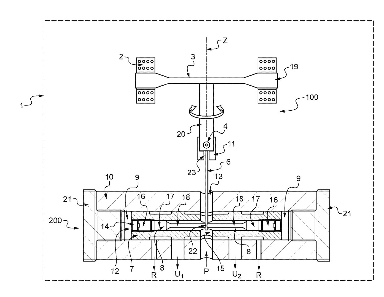
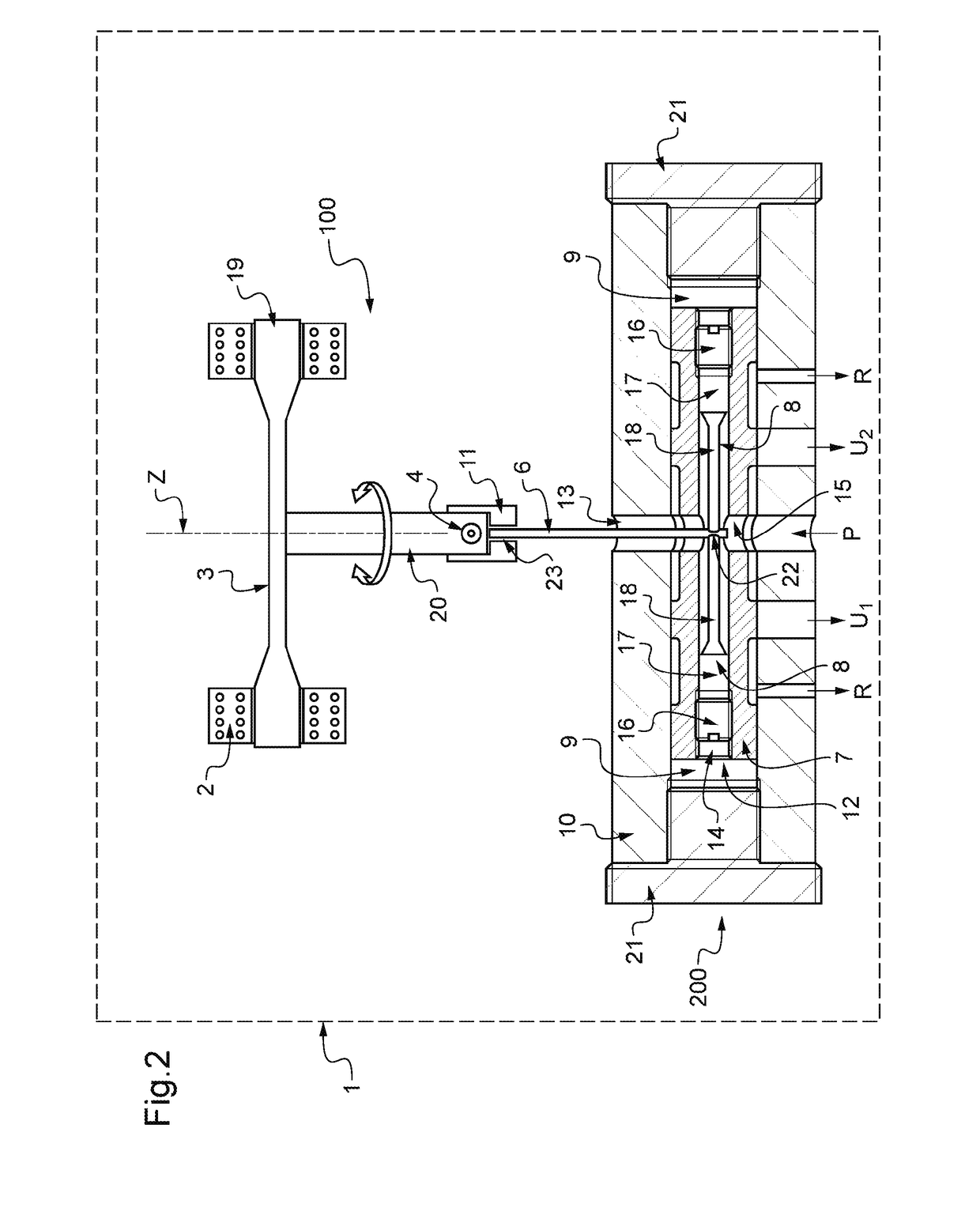
[0023]With reference to FIGS. 1 and 2, the servovalve given overall reference 1 comprises a pilot stage 100 and a power stage 200. The pilot stage 100 has a torque motor comprising TM a stator 2 and a rotor 3. The stator 2 has a stage surrounding the rotor 3, which turns about the axis Z. The rotor 3 has two main elements:[0024]a magnetic flapper 19 subjected to the magnetic field developed by the stator 2 and movable relative to the body of the servovalve 1; and[0025]a column 20 secured to the magnetic flapper 19 and extending along the axis Z, projecting from the stator and penetrating into the inside of the servovalve body.

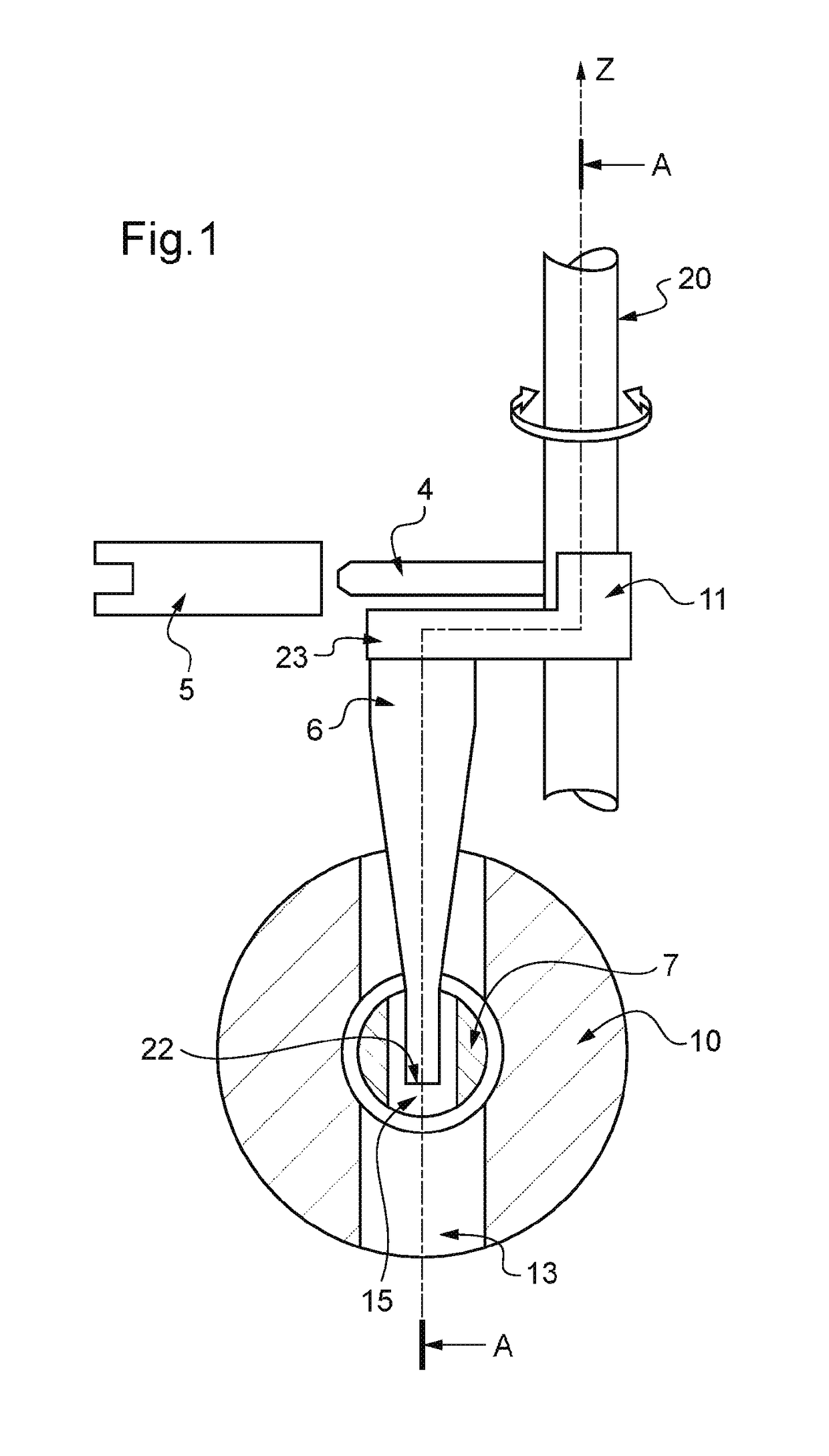
[0026]The column 20 carries a fluid ejector 4 that faces a stationary receiver 5. The column 20 is fed with fluid and the fluid ejector 4 sends a jet of hydraulic fluid towards the stationary receiver 5 along an angular orientation that is a function of the movement of the rotor 3. The column 20 is coupled to a resilient return member (not shown) urging it towa...


PUM


Abstract

A hydraulic servovalve having two stages and feedback members in which the movable power distribution member has clamp means for clamping the feedback member, while allowing a clamped portion of the feedback member at least one freedom of movement relative to the movable distribution member.

Description

CROSS REFERENCE TO RELATED APPLICATIONS[0001]This application is a National Stage of International Application No. PCT / EP2012 / 069860, filed on Oct. 8, 2012, which claims priority from French Patent Application No. 11 59209, filed on Oct. 12, 2011, the contents of all of which are incorporated herein by reference in their entirety.FIELD OF THE INVENTION[0002]The invention relates to a servovalve pilot stage capable of acting as a first stage in a two-stage servovalve.STATE OF THE ART[0003]A conventional servovalve is constituted by a pilot stage piloting a movable power distribution member of a power stage. The function of the power stage is to deliver a pressure or a flow rate proportional to an instruction transmitted to the pilot stage.[0004]The pilot stage has two hydraulic elements, namely a hydraulic emitter (nozzle or ejector) and a hydraulic receiver (fixed receiver, deflector, or flapper) such that modifying their relative position generates pressure differences that are use...

Claims


Application Information

Patent Timeline
Patent Type & Authority Patents(United States)
IPC IPC(8): F15B13/043F15B9/07F15B9/06F15B13/16
CPCF15B13/043F15B9/06F15B9/07F15B13/0436F15B13/16Y10T137/2409
Inventor OZZELLO, GUYLAIN
Owner SAFRAN AEROSYSTEMS HYDRAULICS
Why Eureka
Try Eureka