Pressure sensor having diaphragm

a technology of pressure sensor and diaphragm, which is applied in the direction of fluid pressure measurement using piezoelectric devices, rapid change measurement, instruments, etc., can solve the problem of hysteresis of sensor characteristics becoming much smaller, and achieve excellent linearity and sensitivity without hysteresis, high linearity, and high sensitivity

Active Publication Date: 2005-08-23
DENSO CORP
View PDF2 Cites 5 Cited by
  • Summary
  • Abstract
  • Description
  • Claims
  • Application Information

AI Technical Summary

Benefits of technology

[0005]In view of the above-described problem, it is an object of the present invention to provide a pressure sensor with a diaphragm having high sensitivity, high linearity and small hysteresis.
[0007]In the above sensor, the gauge resistor is larger than the boss from the top view of the boss and the gauge resistor so that the boss is covered with the gauge resistor. Therefore, the portion, at which the stress is concentrated to become maximum, is overlapped with the gauge resistor so that the maximum stress near the outer circumference of the boss is applied to the gauge resistor completely. Accordingly, the characteristics of the relationship between the load and the resistance change of the gauge resistor have excellent linearity, and further, the sensitivity of the sensor shows no fluctuation substantially so that the gauge resistor can detect the small load even when the small load is applied to the sensor. Furthermore, the hysteresis of the sensor characteristics becomes much smaller. Thus, the above sensor has high sensitivity, high linearity and small hysteresis.
[0010]In the above sensor, the gauge resistor is larger than the boss so that the maximum stress near the outer circumference of the boss is applied to the gauge resistor completely. Accordingly, the characteristics of the relationship between the load and the resistance change of the gauge resistor have excellent linearity and sensitivity without hysteresis. Thus, the above sensor has high sensitivity, high linearity and small hysteresis.

Problems solved by technology

Furthermore, the hysteresis of the sensor characteristics becomes much smaller.

Method used


Image

  • Pressure sensor having diaphragm
  • Pressure sensor having diaphragm
  • Pressure sensor having diaphragm

Examples


Embodiment Construction

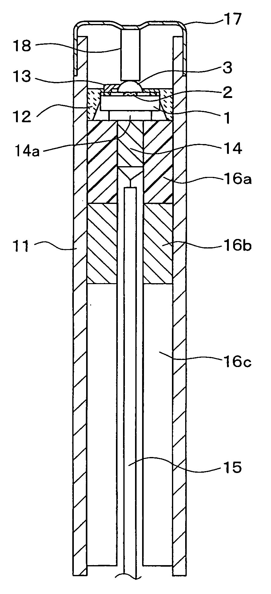
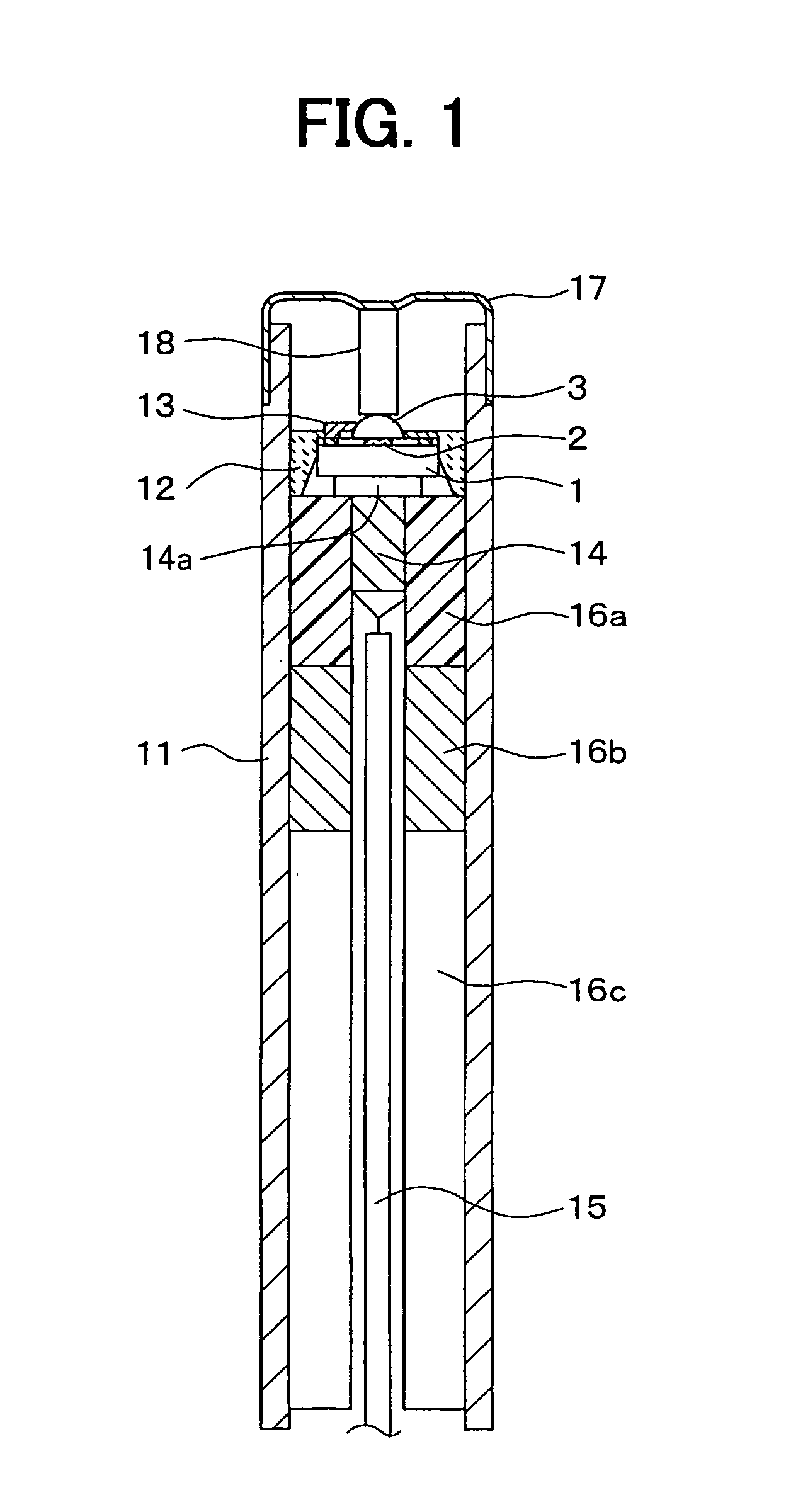
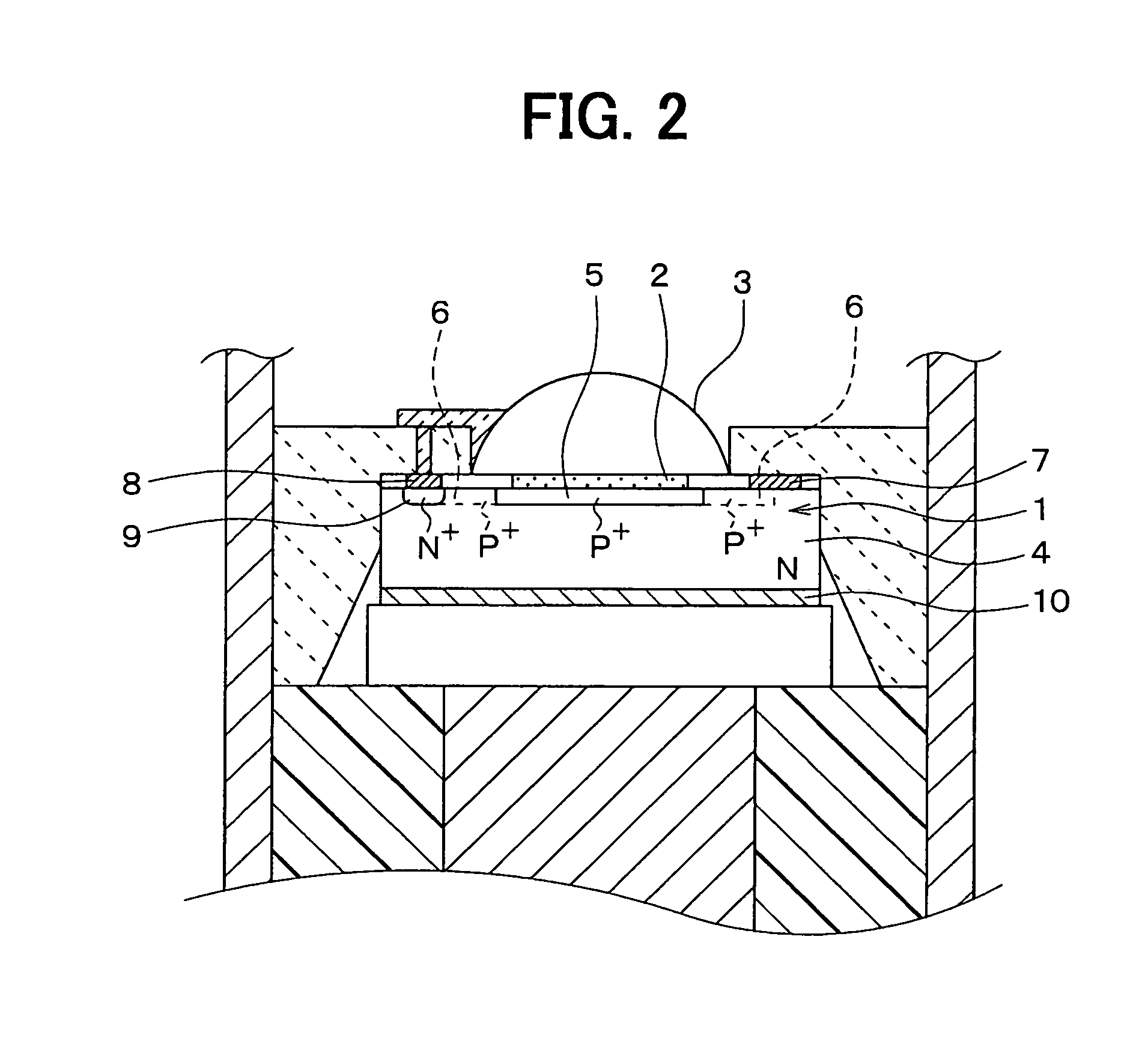
[0024]The inventors have preliminarily studied about a pressure sensor for detecting pressure on the basis of a resistance change of a gauge resistance in accordance with a mechanical load corresponding to the pressure as a measurement object. The sensor is shown in FIG. 11. The sensor includes a sensor chip J1, and a hemispherical member J3, which is disposed on the sensor chip J1.

[0025]The sensor chip J1 has an N conductive type silicon substrate J4 as a base, a gauge resistor J5, an insulation film J6, a P+ conductive type contact portion J7, a pair of electrodes J8, J9, an N+ conductive type layer J10 and a backside electrode J11. The gauge resistor J5 is formed on a surface of the substrate J4. The insulation film J6 is disposed on the surface of the gauge resistor J5. The contact portion J7 protrudes from the gauge resistor J5 in the silicon substrate J4. The backside electrode J11 is disposed on the backside of the substrate J4.

[0026]The hemispherical member J3 is composed of...


PUM

PropertyMeasurementUnit
thicknessaaaaaaaaaa
thicknessaaaaaaaaaa
thicknessaaaaaaaaaa

Abstract

A pressure sensor includes: a casing; a sensor chip with a gauge resistor; a boss disposed on the gauge resistor; a metallic diaphragm capable of distorting in accordance with a pressure; and a load transmission member disposed between the metallic diaphragm and the boss. The casing accommodates the sensor chip, the boss and the load transmission member. The casing is covered with the metallic diaphragm. The pressure applied to the diaphragm is detected such that the load corresponding to the pressure is applied to the gauge resistor through the metallic diaphragm, the load transmission member and the boss so that the pressure is measured on the basis of a resistance change of the gauge resistor. The gauge resistor is larger than the boss.

Description

CROSS REFERENCE TO RELATED APPLICATION[0001]This application is based on Japanese Patent Application No. 2004-26953 filed on Feb. 3, 2004, the disclosure of which is incorporated herein by reference.FIELD OF THE INVENTION[0002]The present invention relates to a pressure sensor having a diaphragm.BACKGROUND OF THE INVENTION[0003]A pressure sensor detects pressure on the basis of a resistance change of a gauge resistor in accordance with a load, which is directly transmitted to the gauge resistor. Here, the pressure as a measurement object distorts a diaphragm, and then, the distortion of the diaphragm is directly transmitted to the gauge resistor as the load through a load transmission member. This type pressure sensor is disclosed in, for example, U.S. Pat. No. 5,349,873.[0004]In the above sensor, when the load applied to the sensor is relatively small, the resistance change is small. Therefore, in this small load region, the sensor shows a small sensitivity so that the sensor does ...

Claims


Application Information

Patent Timeline
Patent Type & Authority Patents(United States)
IPC IPC(8): G01L9/04G01L19/04G01L9/00G01L9/06G01L9/08G01L1/16G01L1/18G01L23/18G01L23/22
CPCG01L1/18G01L9/0042G01L9/0058G01L23/18G01L23/22
Inventor TANAKA, HIROAKITOYODA, INAOSUZUKI, YASUTOSHI
Owner DENSO CORP
Why Eureka
Try Eureka