Optical Receiver and Method of Detecting Loss of Optical Signal of the Optical Receiver

a technology of optical receiver and optical receiver, which is applied in the direction of electrical equipment, transmission monitoring/testing/fault-measurement systems, and electrical transceivers. it can solve the problems of ineffective display of hysteresis characteristic of the signal of detection of loss of optical signal and inability to detect loss of optical signal. achieve high precision

Active Publication Date: 2009-12-10
LUMENTUM JAPAN INC
View PDF4 Cites 5 Cited by
  • Summary
  • Abstract
  • Description
  • Claims
  • Application Information

AI Technical Summary

Benefits of technology

[0010]The present invention has been made in view of the problem described above. An object of the present invention is to provide an optical re

Problems solved by technology

According to the conventional technology described above, there is a case where the hysteresis characteristic of the signal of detection of loss of optical signal is not effectively exhibited based on the first determination signa

Method used


Image

  • Optical Receiver and Method of Detecting Loss of Optical Signal of the Optical Receiver
  • Optical Receiver and Method of Detecting Loss of Optical Signal of the Optical Receiver
  • Optical Receiver and Method of Detecting Loss of Optical Signal of the Optical Receiver

Examples


Embodiment Construction

[0030]Hereinafter, a preferred embodiment for embodying of the present invention (hereinafter referred to as embodiment) is described with reference to the attached drawings.

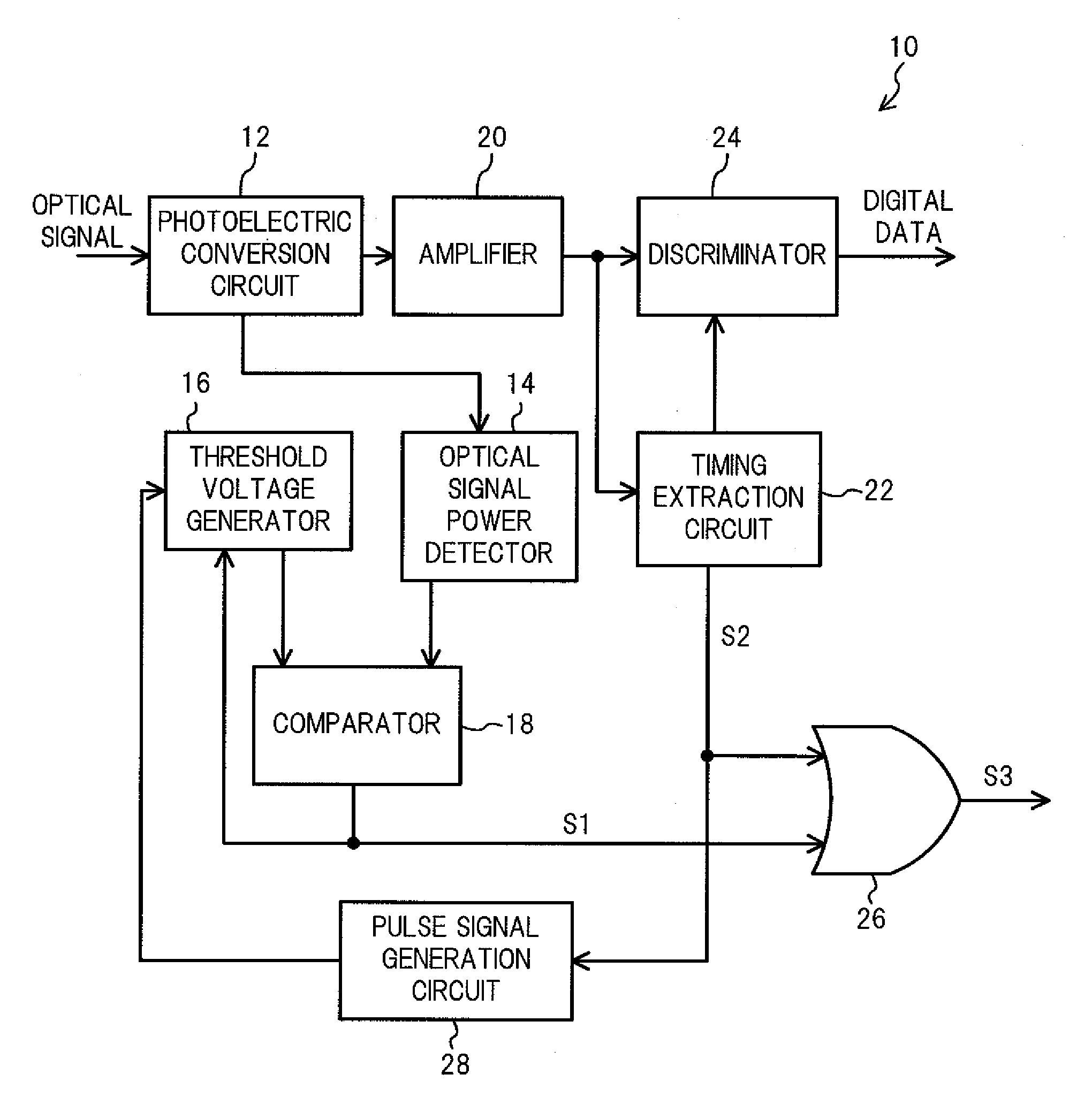
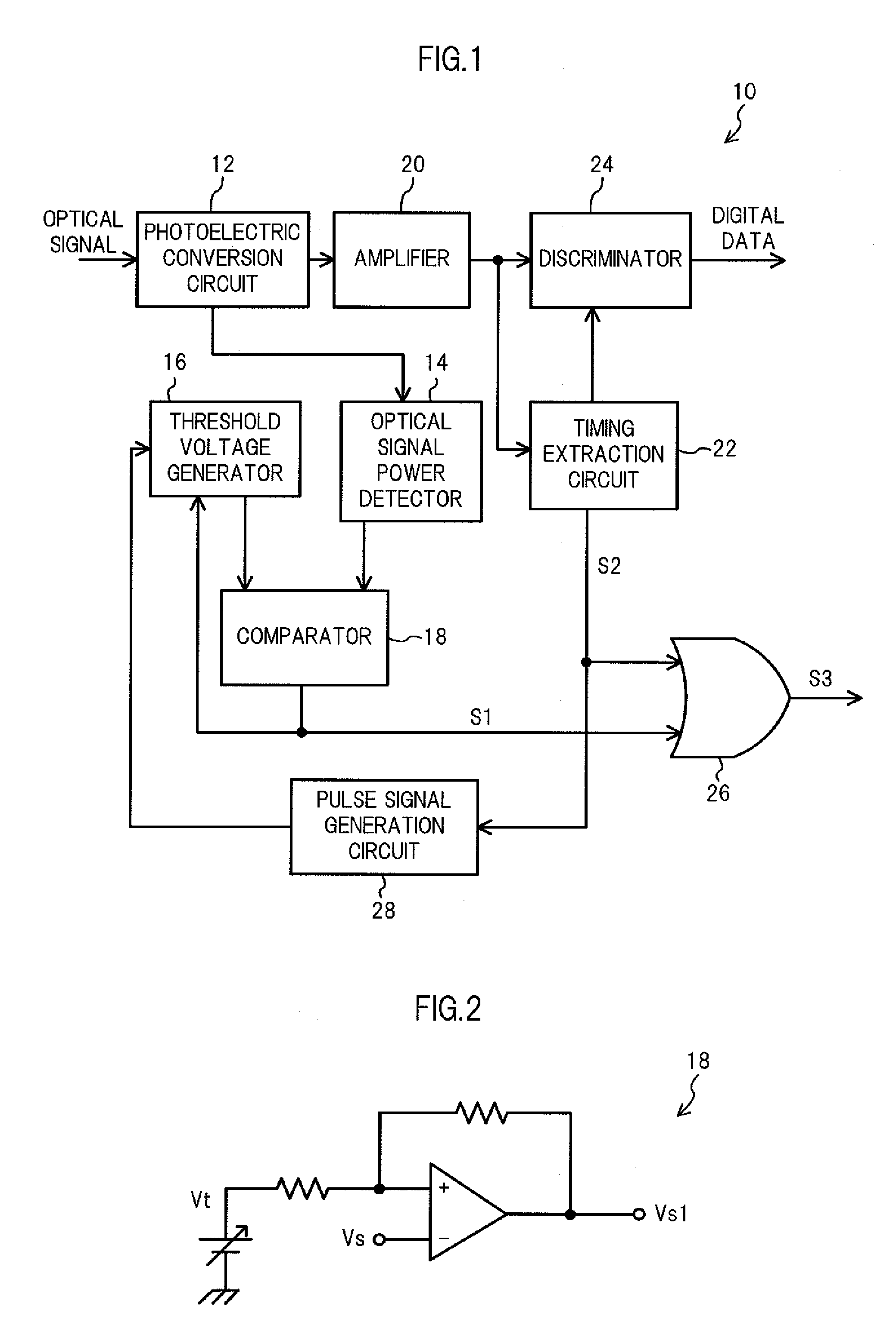
[0031]FIG. 1 is a system structural diagram illustrating an optical receiver 10 according to this embodiment. As illustrated in FIG. 1, the optical receiver 10 includes a photoelectric conversion circuit 12, an optical signal power detector 14, a threshold voltage generator 16, a comparator 18, an amplifier 20, a timing extraction circuit 22, a discriminator 24, an optical signal loss detector 26, and a pulse signal generation circuit 28.

[0032]The photoelectric conversion circuit 12 is a circuit which includes a light receiving element for receiving an optical signal and converts the received optical signal into an electrical signal.

[0033]The optical signal power detector 14 detects a voltage value corresponding to an optical current flowing through the photoelectric conversion circuit 12 by the received optical...


PUM


Abstract

The optical receiver includes: a photoelectric conversion circuit for receiving an optical signal and converting the received optical signal into an electrical signal; a comparator for outputting a first determination signal (S1) when a voltage corresponding to the optical signal does not reach a first threshold value (TH1) and for canceling an output of the S1 when the voltage corresponding to the optical signal exceeds a second threshold value larger than TH1 during the S1 is output; a timing extraction circuit for generating a clock signal based on a frequency and a phase of the electrical signal obtained by the converting and for outputting a second determination signal (S2) when the generated clock signal does not satisfy a predetermined condition; a unit for causing the comparator to output the S1 when the S2 is output; and detects loss of optical signal while one of the S1 and S2 is output.

Description

CROSS-REFERENCE TO RELATED APPLICATION[0001]The present application claims priority from Japanese application JP 2008-146589 filed on Jun. 4, 2008, the content of which is hereby incorporated by reference into this application.BACKGROUND OF THE INVENTION[0002]1. Field of the Invention[0003]The present invention relates to an optical receiver and a method of detecting loss of optical signal of the optical receiver.[0004]2. Description of the Related Art[0005]In an optical receiver for receiving an optical signal transmitted in an optical transmission system, when the received optical signal is lowered in level or is lost, detection of loss of optical signal is performed for detecting such a state. It is very important to perform the detection of loss of optical signal with high precision in order to improve the reliability of data transmission. A conventional technology for performing the detection of loss of optical signal in the optical receiver is, for example, a technology descri...

Claims


Application Information

Patent Timeline
IPC IPC(8): H04B10/06H04B10/07H04B10/079H04B10/40H04B10/50H04B10/60
CPCH04B10/69H04B10/0799
Inventor FURUKAWA, MASAAKISAGARA, KOUHEI
Owner LUMENTUM JAPAN INC
Why Eureka
Try Eureka