Electric door opener for glass doors

Inactive Publication Date: 2008-06-12
ASSA ABLOY SICHERHEITSTECHN
View PDF9 Cites 5 Cited by
  • Summary
  • Abstract
  • Description
  • Claims
  • Application Information

AI Technical Summary

Benefits of technology

[0008]In order to prevent jamming during the insertion of the door into the receiving region, the mating holder can be provided with a resilient configuration. The door opener can also be arranged in such a way that it is fastened by means of oblong holes to a closing plate. The oblong holes can be arranged either on the door opener or on the closing plate.
[0009]The receiving region is provided with a substantially U-shaped arrangement in a preferred embodiment. The arrangement of the receiving region in this shape is appropriate because it corresponds to most of the standard profiles of glass doors and the receiving region and the door leaf can thus cooperate best together. One leg of a U is appropriately formed in this embodiment by the holder and the other leg by the mating holder. The region connecting the area of the two legs of the U can be formed either by the latch body, the holder or the mating holder. The U-shaped arrangement of the receiving region ensures that a secure overlap occurs of the edge of the door leaf in the closed position.
[0010]The holder is arranged with an L-shaped profile in a further preferred embodiment. The one L-leg is used for laterally delimiting the receiving region and the other leg as the guide surface and rests on the latch body. The holder with the L-shaped profile is used especially preferably in a receiving region arranged in a U-shaped manner, with one L-leg of the holder forming the connection between the two legs of the U of the receiving region and thus being opposite to the face surface of the door leaf in the closed position.
[0011]The movement of the holder during the displacement appropriately occurs in a substantially linear way. When the receiving region is arranged in a U-shaped manner, it is further appropriate that the holder is movable along the plane of the receiving region which connects the two legs of the U. In this way, one of the legs of the U of the receiving region can be displaced parallel to the other leg of the U, as a result of which the width of the receiving region is adjustable. In a further preferred embodiment, the holder is displaceable fastened to the latch body. The adjustment of the holder for the adjustability of the width of the receiving region can thus be performed in an especially simple way. The displaceable fastening of the holder to the latch body can be arranged in such a way that the holder can be displaced when in direct contact with the latch body along the surface of the latch body. The two contact surfaces of holder and latch body are appropriately provided with a planar configuration in this embodiment. The displacement can also occur in such a way for example that the holder is dismounted from the latch body from an initial position and is mounted again at a new p

Problems solved by technology

Moreover, excessive play redu

Method used


Image

  • Electric door opener for glass doors
  • Electric door opener for glass doors
  • Electric door opener for glass doors

Examples


Embodiment Construction

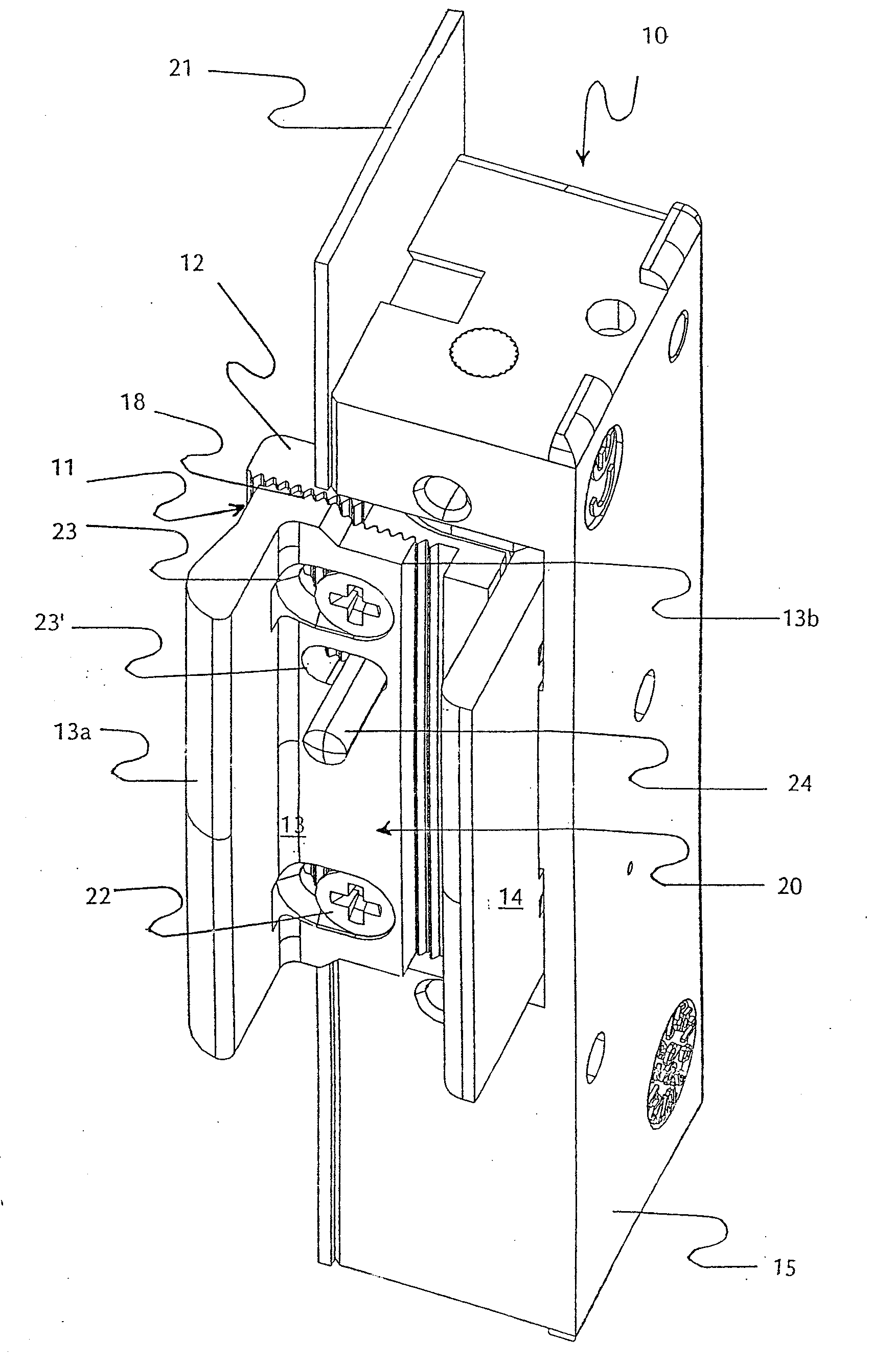
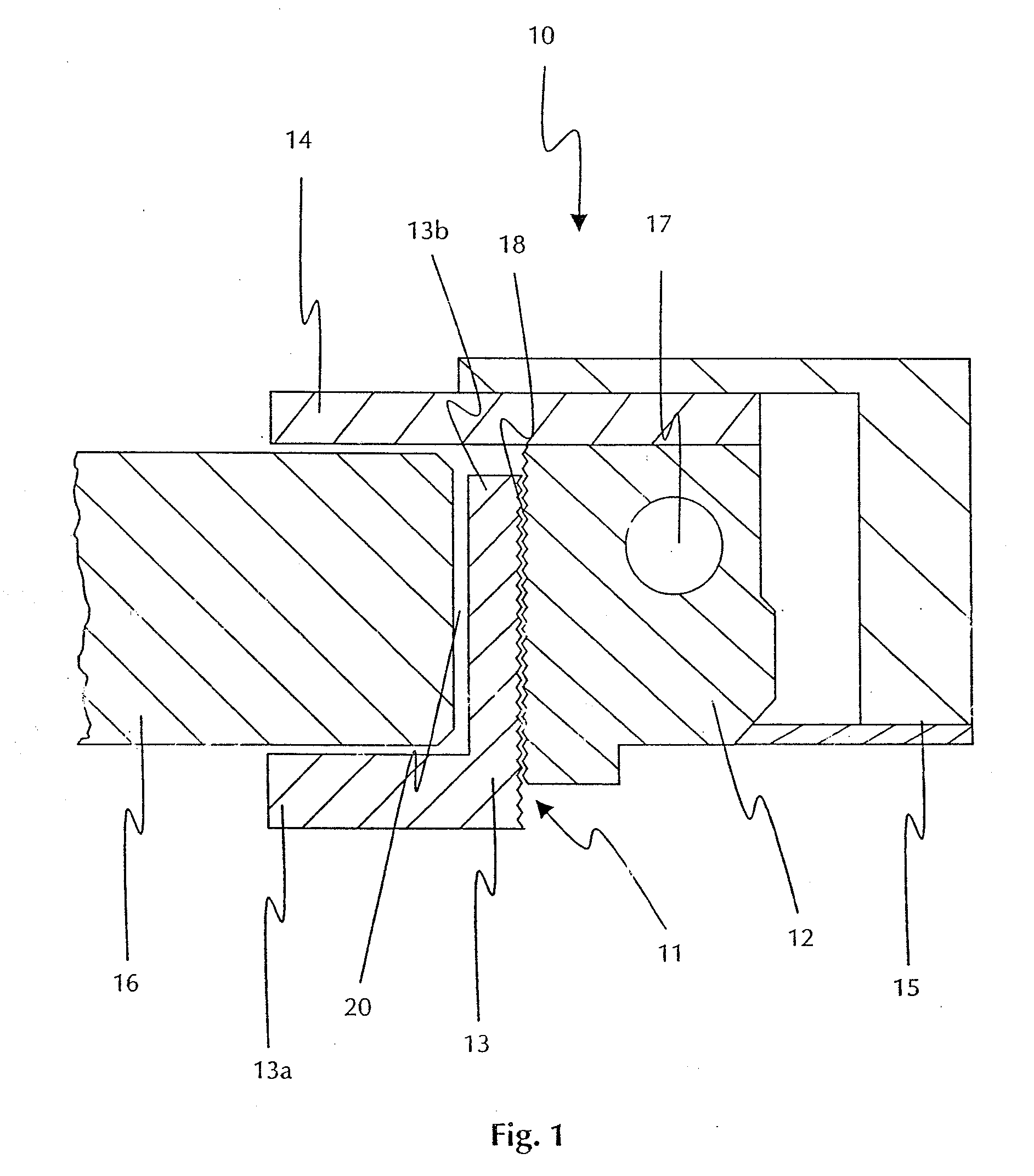
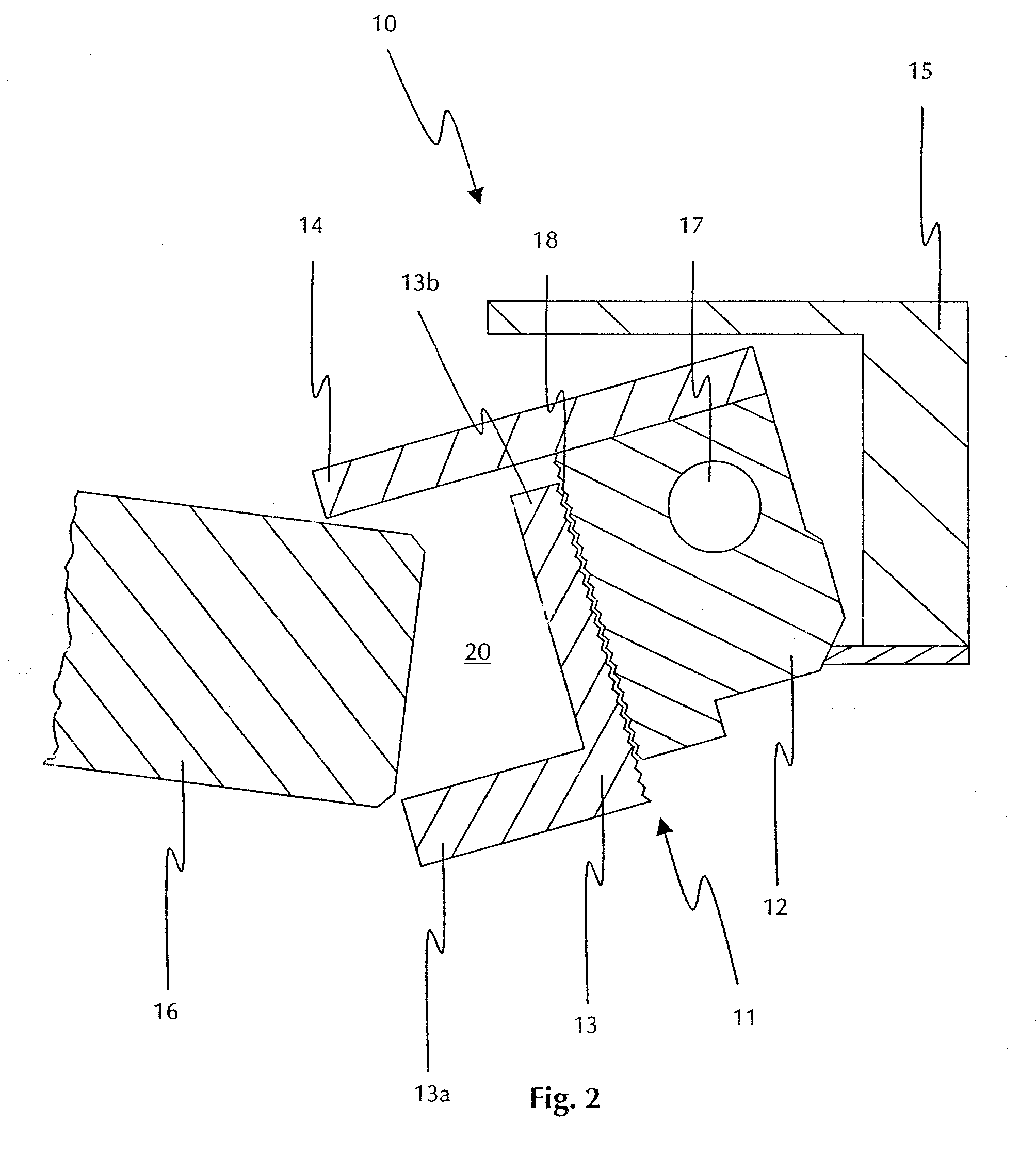
[0028]FIG. 1 shows a sectional view of a door opener 10 for glass doors. The door opener 10 is in the closed position. The door opener latch 11 is pivotably held on a pivoting axle 17. The door opener 10 comprises a door opener housing 15 in which the latch 11 is arranged. The door opener latch 11 consists of a latch body 12 and an L-shaped holder 13 whose one arm 13a of the L forms the one leg of the U of the U-shaped receiving region 20 and whose other arm 13 of the L acts as a bearing surface and rests on the latch body 12. The contact surfaces of the arm 13b and the latch body 12 which rest on each other are arranged as a tooth grid 18. The holder 13 can be adjusted along the tooth grid 18, with the distance between two teeth predetermining the length of one adjustment step each.

[0029]The U-shaped receiving region 20 is also delimited by the arm 13b and the mating holder 14 in addition to the arm 13a of holder 13, with the mating holder 14 and the arm 13a forming the legs of the...


PUM


Abstract

The invention describes an electric door opener for glass doors, having a pivotable door opener latch comprising a holder, and a mating holder, with the holder and the mating holder delimiting a receiving region for receiving a glass door leaf. In order to simplify installation and improve storage, the door opener is designed such that the holder is provided with an adjustable configuration to ensure adjustability of the width of the receiving region.

Description

CROSS-REFERENCE TO RELATED APPLICATIONS[0001]This application is a continuation of International Application No. PCT / EP2006 / 004503 filed on May 12, 2006, which designated the United States, which application claims priority of DE 102005028957.6 filed Jun. 22, 2005. The disclosure of each application is hereby incorporated by reference in their entirety.BACKGROUND OF THE INVENTION[0002]The invention relates to an electric door opener for glass doors, comprising a pivotable door opener latch comprising a holder, and a mating holder, with the holder and the mating holder delimiting a receiving region for receiving a glass door leaf.[0003]As is generally known, door openers are used in door closing systems of residential or office buildings. Electric door openers generally comprise a pivot latch which can be released or blocked by means of a stop lever (switchover) through an electric positioning element, especially an electromagnet.[0004]Glass doors for installation in buildings were u...

Claims


Application Information

Patent Timeline
IPC IPC(8): E05F15/00
CPCE05B15/0245E05B15/025E05C3/24E05B63/0052E05B65/0025E05B47/0047Y10T292/699
Inventor WITTKE, NORMAN
Owner ASSA ABLOY SICHERHEITSTECHN
Why Eureka
Try Eureka