Bearing Device, Stage Device, and Exposure Apparatus

a technology of stage device and bearing device, applied in the direction of photomechanical equipment, instruments, printers, etc., to achieve the effect of sufficient moving strok

Inactive Publication Date: 2008-06-26
NIKON CORP
View PDF8 Cites 10 Cited by
  • Summary
  • Abstract
  • Description
  • Claims
  • Application Information

AI Technical Summary

Benefits of technology

[0020]As described above, according to the present invention, without being subject to restrictions relating to supply of a medium and without connecting a tube, etc. for supply of air, the length of the movable body can be set freely and a sufficient moving stroke can be secured. Moreover, according to the present invention, without being subject to restrictions relating to supply of a medium, a substrate can be moved at an arbitrary stroke required for exposure processing.

Problems solved by technology

However, since the above configuration needs to be connected to a tube, etc. for supply of air to the movable body, durability of the tube or a space for bending or leading the tube around will be required.

Method used


Image

  • Bearing Device, Stage Device, and Exposure Apparatus
  • Bearing Device, Stage Device, and Exposure Apparatus
  • Bearing Device, Stage Device, and Exposure Apparatus

Examples


first embodiment

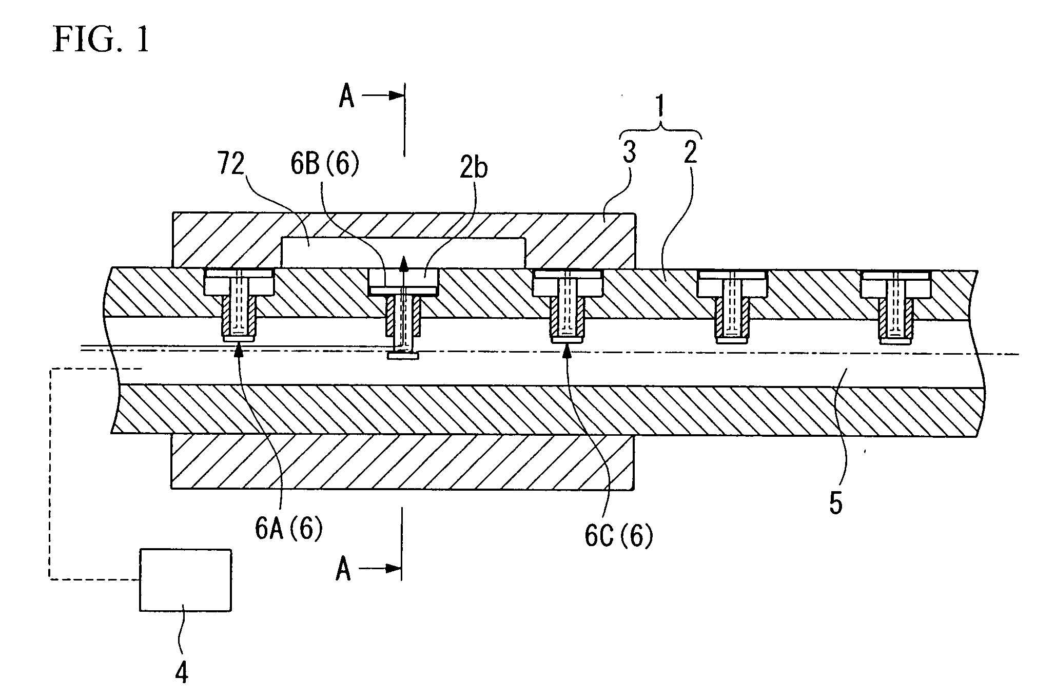
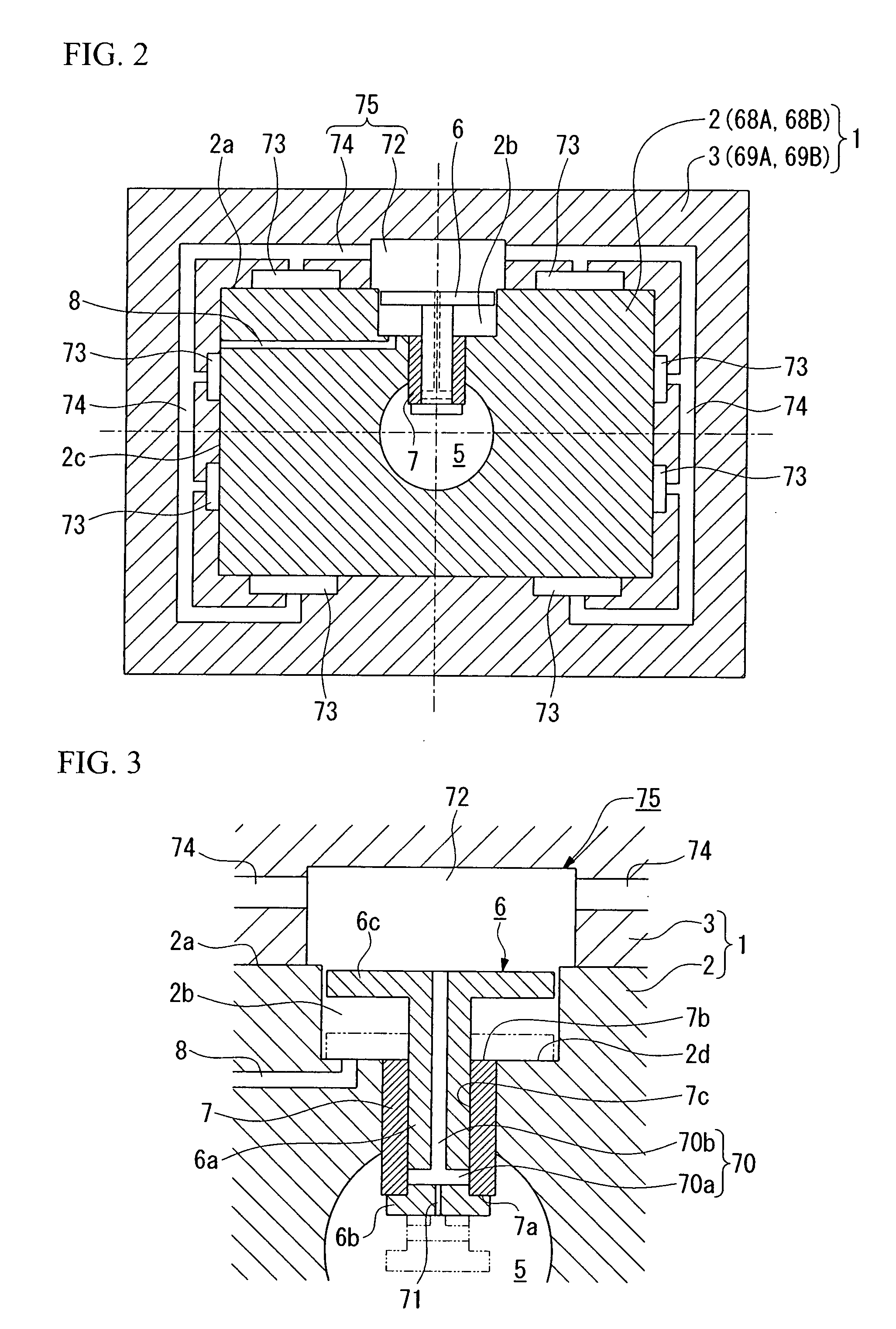
[0056]FIG. 1 is a sectional view showing one embodiment of the bearing device, and FIG. 2 is a sectional view taken along a line A-A in FIG. 1.

[0057]The bearing device 1 shown in these drawings is mainly composed of a guide shaft (fixed body) 2 extending in the right and left directions in FIG. 1 and having a rectangular cross-section (refer to FIG. 2), and a table (movable body) 3 which is formed in a rectangular cylinder shape in cross-section, and which is fitted to the guide shaft 2 with an infinitesimal gap and is movably supported by the guide shaft.

[0058]An air supply passage (supply part) 5 having a round cross-section, to which air as a medium is supplied, is formed at the inner center of the guide shaft 2 along the longitudinal direction. To the air supply passage 5 is supplied air from an air supply source 4 and with, for example, a pressure of about 0.5 MPa, which is greater than the atmospheric pressure. Moreover, a plurality of pilot valves (opening and closing units) ...

second embodiment

[0079]Next, a second embodiment of the bearing device will be described.

[0080]Although the first embodiment has a configuration in which the pilot valve 6 is activated by the air pressure of the air reservoir 72 provided in the table, the present embodiment has a configuration in which a pilot valve is driven by a magnetic force using a magnet. This configuration will be described with reference to FIG. 5. In FIG. 5, the same constituent parts as those of the first embodiment shown in FIGS. 1 to 4D are denoted by the same reference numerals, and the description thereof is omitted.

[0081]In the present embodiment, the pilot valve 6 (even in the present embodiment, pilot valves are denoted by 6A, 6B, and 6C from the left in FIG. 6) is composed of the shank 6a, the engaging part 6b, and an N-pole magnet 76N and an S-pole magnet 76S which are sequentially provided at the top end of the shank 6a. An introducing hole 70c which communicates with the introducing hole 70a formed in the shank ...

third embodiment

[0088]Although the first and second embodiments have a configuration in which air is used as a medium, the present embodiment has a configuration in which a vacuum as media is supplied to (is formed in) a vacuum-preloaded air pad (actually, a vacuum state is supplied to the air pad by air being sucked by vacuum suction from the air pad). An example of this configuration will be described with reference to FIG. 6.

[0089]In the present embodiment, a vacuum suction passage 5A as a vacuum supply part connected to a vacuum suction source 4A is provided in the guide shaft 2. A bush 7A which fits to the shank 6a of the pilot valve 6 is provided in this vacuum suction passage 5A so as to protrude thereinto. The bush 7A is formed with a communicating hole 7B which communicates with the introducing hole 70a formed in the pilot valve 6 and is opened to the vacuum suction passage 5A when the pilot valve 6 ascends upwards and the bush engages an engaging part (not shown), and which is released fr...


PUM


Abstract

A sufficient moving stroke can be secured without connecting a tube, etc. for supply of air. A movable body (3) having a pad part (73) and a fixed body (2) are provided. The movable body (3) is movably supported by the fixed body (2) by supplying the medium to the pad part (73). A supply part (5) which is provided in the fixed body (2) and to which the medium is supplied; a connecting part (75) which connects the supply part (5) with the pad part (73); and an opening and closing unit (6) which opens and closes the connecting part (75) according to the position of the movable body (3) with respect to the fixed body (2), are provided.

Description

TECHNICAL FIELD[0001]The present invention relates to a bearing device which movably supports a movable member using a medium, and a stage device and an exposure apparatus in which the movable body is supported by this bearing device.[0002]This application claims priority to Japanese Patent Application No. 2004-302699 filed Oct. 18, 2004, the entire contents of which are incorporated herein by reference.BACKGROUND ART[0003]In a lithography process for manufacturing semiconductor devices, liquid crystal display substrates, etc., an exposure apparatus is used, which transfers and exposes a pattern on a reticle as a mask to each shot region, such as a wafer or a glass substrate, on which a photoresist is coated.[0004]In this type of exposure apparatus, many configurations are adopted in which, as a guide mechanism when a movable body such as a reticle stage or a wafer stage moves, movement of the movable body is supported using a bearing device, are adopted.[0005]Conventionally, as a b...

Claims


Application Information

Patent Timeline
Patent Type & Authority Applications(United States)
IPC IPC(8): G03B27/58F16C32/06F16K31/00F16C29/02
CPCF16C29/025G03F7/70816F16C32/064G03F7/70716
Inventor ARAI, DAI
Owner NIKON CORP
Why Eureka
Try Eureka