Edge Gated Injection Molding Apparatus

a technology of injection molding apparatus and valve pin, which is applied in the field of valve pin mechanism for use in the edgegated injection molding apparatus, can solve the problems of lateral gate melt imbalance and the discovery of the valve pin mechanism

Active Publication Date: 2008-06-26
MOLD MASTERS 2007
View PDF17 Cites 35 Cited by
  • Summary
  • Abstract
  • Description
  • Claims
  • Application Information

AI Technical Summary

Benefits of technology

[0011]Embodiments of the present invention will now be described more fully with referen

Problems solved by technology

U.S. Published Application Publication No. 2005-0196486 does not disclose a valve pin mechanism for opening and closing communication to the mold gates.
In such an arrangem

Method used


Image

  • Edge Gated Injection Molding Apparatus
  • Edge Gated Injection Molding Apparatus
  • Edge Gated Injection Molding Apparatus

Examples


Embodiment Construction

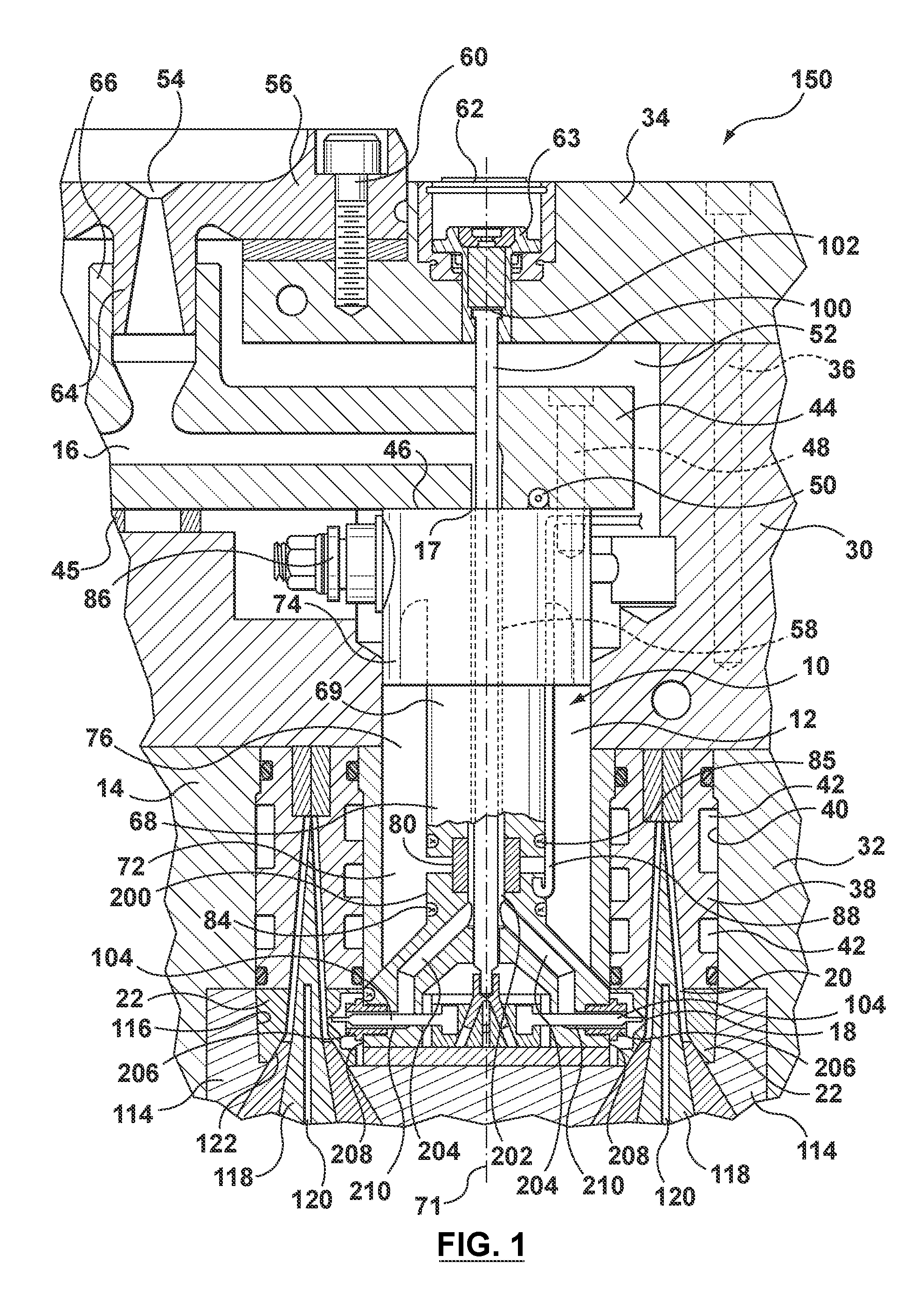
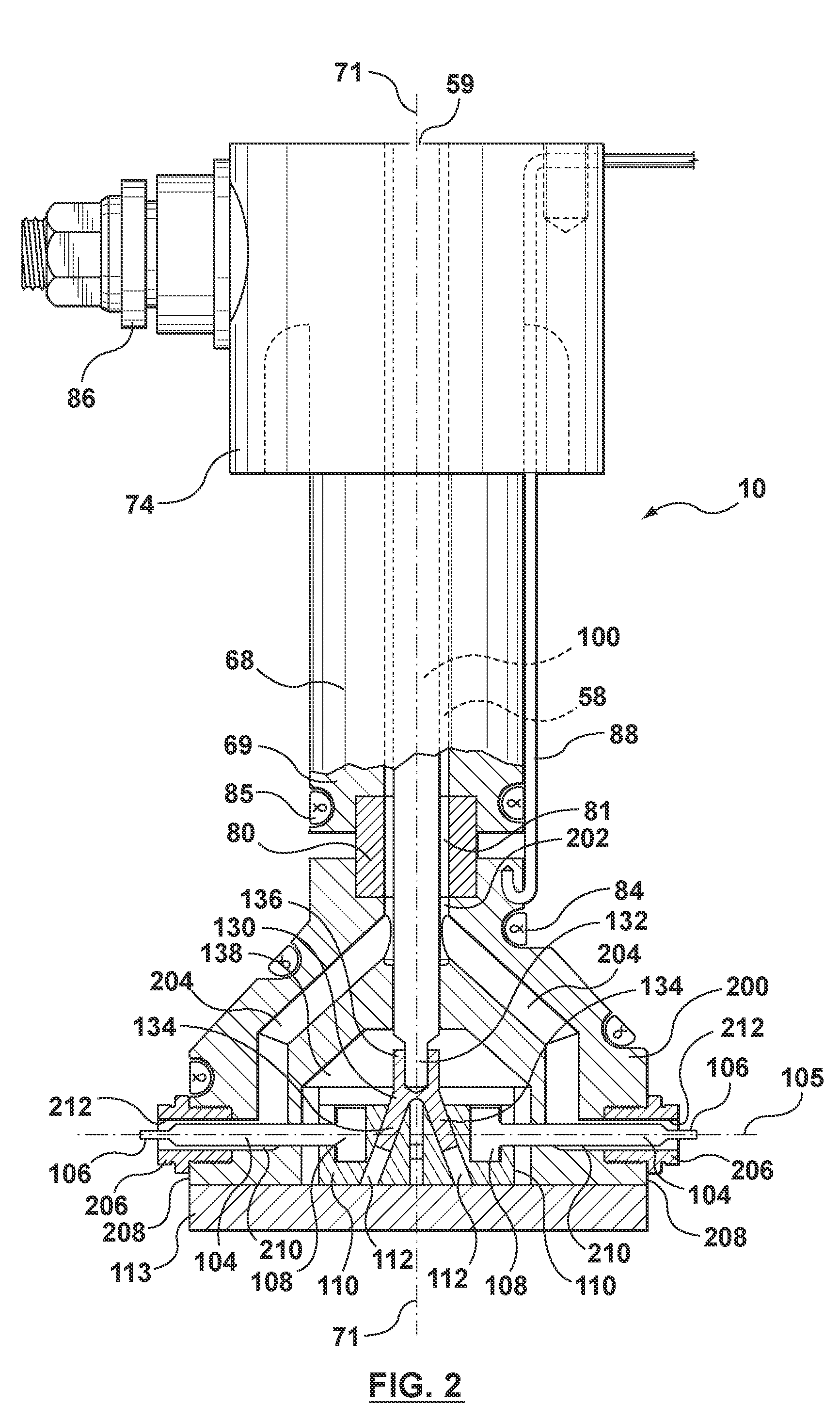
[0025]A partial sectional view of an injection molding apparatus in accordance with the present invention is illustrated in FIG. 1 and is generally indicated by reference numeral 150. FIGS. 2 and 3 show an enlarged view of a nozzle 10 of injection molding apparatus 150 of FIG. 1. Injection molding apparatus 150 includes a melt distribution manifold 44 that is located between a spacer plate 30 and a back plate 34. While molds have a wide variety of configurations, in this case spacer plate 30 is mounted between a cavity plate 32 and back plate 34 which are secured together by bolts 36 in a conventional manner. Spacer plate 30 and cavity plate 32 are aligned by dowel pins (not shown). Manifold 44 is supported on the spacer plate 30 by a locating and supporting ring 45. Manifold 44 includes a branched melt channel 16 and is heated by an integral electrical heating element 50. An insulative air space 52 is provided between manifold 44 and the surrounding cooled spacer plate 30 and back ...


PUM

PropertyMeasurementUnit
Angleaaaaaaaaaa

Abstract

An injection molding apparatus includes an injection manifold having an inlet and a melt channel. The manifold melt channel branches to a plurality of melt channel outlets. A hot runner injection nozzle includes an axial melt channel extending along a central axis and communicating with one of the manifold melt channel outlets. The nozzle further includes at least two angled melt channels disposed at an angle to the central axis. At least two nozzle tips are provided, and each includes a nozzle tip melt channel in communication with one of the angled melt channels. A valve pin is disposed at least partially within the axial melt channel coaxially with the central axis and movable within the axial melt channel. Lateral valve pins movable within the nozzle tip melt channels are disposed at an angle to the valve pin. Linkage elements continuously connect the lateral valve pins to the valve pin. Axial movement of the valve pin is transmitted through the linkage elements to the lateral valve pins to open and close communication between the nozzle tip melt channels and the lateral mold gates.

Description

CROSS-REFERENCE TO RELATED APPLICATIONS[0001]This application claims the benefit of U.S. provisional patent application no. 60 / 871,668 filed Dec. 22, 2006, which is hereby incorporated by reference in its entirety herein.BACKGROUND OF THE INVENTION[0002]1. Field of the Invention[0003]The present invention relates generally to an injection molding apparatus and, in particular, to a valve pin mechanism for use in an edge-gated injection molding apparatus.[0004]2. Related Art[0005]Edge gating from a nozzle of an injection molding apparatus through a number of edge gate tips is well known. A multi-cavity edge, or side, gated injection molding apparatus is described in U.S. Pat. No. 5,494,433 to Gellert, issued Feb. 27, 1996, which is incorporated in its entirety herein by reference thereto. Generally, the multi-cavity edge-gated injection molding apparatus includes several nozzles that are coupled to a manifold to receive a melt stream of moldable material therefrom. Each nozzle is moun...

Claims


Application Information

Patent Timeline
IPC IPC(8): B29C45/18
CPCB29C45/2735B29C2045/2831B29C2045/2813B29C45/281
Inventor KLOBUCAR, PETERBABIN, DENIS
Owner MOLD MASTERS 2007
Why Eureka
Try Eureka