Hot runner manifold system

Active Publication Date: 2006-09-14
HUSKY INJECTION MOLDING SYST LTD
View PDF4 Cites 22 Cited by
  • Summary
  • Abstract
  • Description
  • Claims
  • Application Information

AI Technical Summary

Benefits of technology

[0012] The invention provides the opportunity for flow paths in such manifolds to be routed where needed without regard to nozzle location. The invention also provides the opp

Problems solved by technology

However, for molds with a high number of cavities, such uniform flow paths are not always possible due to location limitations on the manifold.
Such prior art manifold systems have significant limitations and shortcomings.
Such a flo

Method used


Image

  • Hot runner manifold system
  • Hot runner manifold system
  • Hot runner manifold system

Examples


Embodiment Construction

)

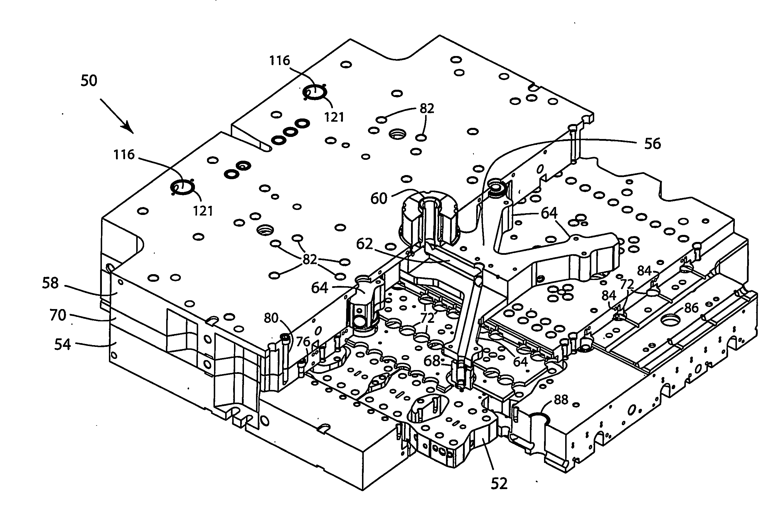
[0023] Referring to FIGS. 3-5, an example of the preferred embodiment of a manifold assembly of the present invention is illustrated and generally indicated by the reference numeral 50. The hot runner manifold system 50 has a plurality of sub-manifolds 52 that are preferably arranged and housed in manifold plate 54 and are fed by a main manifold 56 preferably housed in backing plate 58. As with the prior art manifolds, a sprue 60 connects to the main manifold 56 at a central location, and main manifold 56 has a main melt channel 62 that branches into arms 64 of main manifold 56. Arms 64 may branch in several different directions, such as is illustrated, or a manifold may have only two arms aligned and extending opposite from each other and from sprue 60 to make a linear manifold. The manifold may also have only one arm, which in that case, functions to offset the flow in one direction only. Each arm has an outlet 63 of a branch of the main melt channel 62 that is in communication w...


PUM

PropertyMeasurementUnit
Angleaaaaaaaaaa
Melting pointaaaaaaaaaa
Thermal propertiesaaaaaaaaaa

Abstract

A manifold system (50) comprising a main manifold (56) with a plurality of arms (64), a plurality of sub-manifolds (52) spaced from the main manifold (56) and communicating with the main manifold (56) through a plurality of melt transfer bushings (68) disposed between the main manifold (56) and the sub-manifolds (52). The melt transfer bushings (68) may include static mixers (140) to homogenize the melt. An air plate (70) is disposed between a backing plate (58) preferably housing the main manifold (56) and a manifold plate (54) preferably housing the sub-manifolds (52). The air plate (70) has a plurality of air channels (74) that communicate with valve gate nozzle actuators (90), which are received in actuator cavities (72) in the air plate (70). The air plate (70) is bolted to the manifold plate (54), and the backing plate (58) is bolted to the air plate (70) with bolting patterns not constrained by location of the main manifold (56) or sub-manifolds (52). The manifold system (50), as shown in FIG. 5, has better thermal and geometric balance, closer nozzle spacing, and better bolting for less plate bowing.

Description

TECHNICAL FIELD [0001] The present invention relates, generally, to injection molding equipment. More particularly, the invention relates to hot runner manifold systems used for injection molding. The invention has particular utility in large cavitation systems. BACKGROUND OF THEE INVENTION [0002] The state of the art includes various arrangements for hot runner manifold systems to transfer molten material, typically plastic resin, from an injection molding machine to a mold. Hot runner manifold systems are well known and typically include a manifold plate, a manifold housed in the manifold plate, and a backing plate that supports the manifold and manifold plate. The manifold system routes molten material from a central sprue, which connects to an injection unit on an injection molding machine, to a plurality of nozzles which inject the molten material into cavities in the mold. The manifold system divides the flow of the molten material into several branches as it flows from the ce...

Claims


Application Information

Patent Timeline
IPC IPC(8): B29C35/00B29C45/27B29C45/28
CPCB29C45/2725B29C45/2738B29C45/2806B29C2045/273B29C2045/2762B29C2045/308
Inventor SERNIUK, NICHOLASKNAPP, JOHNBOUTI, ABDESLAMJENKO, EDWARD J.
Owner HUSKY INJECTION MOLDING SYST LTD
Why Eureka
Try Eureka