Open Loop Pressure Control For Injection Molding

a technology of pressure control and injection molding, applied in the field of injection molding, can solve the problems of significant influence on the quality attributes of parts, defects related to the dynamics of packing stage, and it is not possible to optimize the pressure for each cavity

Active Publication Date: 2007-12-20
MOLD MASTERS 2007
View PDF52 Cites 21 Cited by
  • Summary
  • Abstract
  • Description
  • Claims
  • Application Information

AI Technical Summary

Benefits of technology

[0015]An injection molding system is provided that includes a manifold having a manifold melt channel and an injection molding nozzle having a nozzle melt channel, wherein the nozzle melt channel is in fluid communication with an outlet of the manifold melt channel. The injection molding system also includes a self-regulating valve partially positioned within the manifold melt channel upstream of the nozzle melt channel. The self-regulating valve includes a valve disk and a control rod slidable within a longitudinal bore in the valve disk. The valve disk has a control rod support extension with a flow aperture in a sidewall thereof. The flow aperture of the control rod support extension of the valve disk is in communication with the manifold melt channel and an opening in a downstream end of the control rod. The control rod further includes a tip pressure surface. The self-regulating valve is configured to regulate a melt stream flowing through the control rod opening from the manifold melt channel to the inlet of the nozzle melt channel. In response to opposing forces that are exerted on the control rod by an external force device acting on a head portion of the control rod and fluid pressure exerted by the melt on the tip pressure surface of the control rod, the control rod slides upwards and / or downwards to balance the melt flow during an injection cycle.

Problems solved by technology

Thus, it is typically not possible to optimize pressure for each cavity by controlling an overall pressure of the injection molding machine.
Also, part quality attributes are significantly affected by the flow-rates and pressures in the injection stage of the molding cycle.
Typical part defects related to the packing stage dynamics are sink, flash, shrinkage, warpage, and residual stress.
One way to provide flow control is to individually re-tool the runner for every new product, but this is expensive and time-consuming.
Such dynamic feed systems impose additional costs in equipment, i.e., require a controller, pressure transducers / sensors, etc. in order to create the required closed-loop feedback system, as well as in operating costs due to the complexity of the systems.
In addition, oftentimes a large portion of the pin, or control rod, is unsupported during operation and subject to deflection that may result in misalignment and reduced service life.
In addition to imposing additional costs associated with the control of the rams and valve pins, the system also creates a secondary interruption in the melt flow.
Such secondary interruptions may create additional imperfections in the molded parts.
Regardless of the mode of operation, this system requires that the spool valve and housing both have complicated geometries.
As a result, these passive systems may also be prone to reduced service lives.

Method used


Image

  • Open Loop Pressure Control For Injection Molding
  • Open Loop Pressure Control For Injection Molding
  • Open Loop Pressure Control For Injection Molding

Examples


Embodiment Construction

[0029]Specific embodiments of the present invention are now described with reference to the figures, where like reference numbers indicate identical or functionally similar elements. Also in the figures, the left most digit of each reference number corresponds to the figure in which the reference number is first used. While specific configurations and arrangements are discussed, it should be understood that this is done for illustrative purposes only. A person skilled in the relevant art will recognize that other configurations and arrangements can be used without departing from the spirit and scope of the invention.

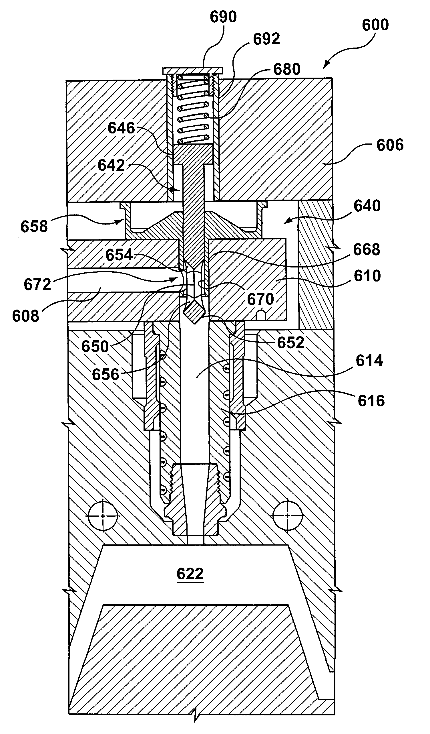
[0030]FIG. 1 shows an injection molding apparatus 100. Injection molding apparatus 100 includes a machine nozzle 102, which introduces a melt stream under pressure into the injection molding system via a sprue bushing 104 that is positioned within a machine platen 106. From sprue bushing 104, melt flows into a manifold melt channel 108 provided in a hot runner manifold 1...


PUM

PropertyMeasurementUnit
angleaaaaaaaaaa
diameteraaaaaaaaaa
diameteraaaaaaaaaa

Abstract

An injection molding system is disclosed having a self-regulating valve for balancing melt flow. The self-regulating valve includes a control rod configured to balance the melt flow rate through a hot runner system. The self-regulating valve reacts to an injection or melt pressure within the hot runner system and a pre-set force provided by an external force device. The self-regulating valve is an open-loop system as it requires neither a measurement of pressure by a sensor nor feedback from a processor in order to regulate the melt flow. The self-regulating valve mechanically reacts to changes in melt pressure on control surfaces thereof by “bobbing” upwards/downwards to decrease/increase the melt flow accordingly. The self-regulating valve compensates for conditions that affect melt pressure, such as an increase/decrease in melt viscosity, changes in melt temperature, and/or mold cavity size without the use of a processing device.

Description

CROSS-REFERENCE TO RELATED APPLICATION[0001]This application claims the benefit under 35 U.S.C. § 119(e) of provisional application U.S. Appl. No. 60 / 814,044, filed Jun. 16, 2006, the disclosure of which is incorporated by reference herein in its entirety.FIELD OF THE INVENTION[0002]The invention relates to injection molding, and particularly to an apparatus and method of open-loop pressure control for balancing the melt flow in a hot runner system.BACKGROUND OF THE INVENTION[0003]Injection molding is a common manufacturing practice. Injection molding is a cyclic process in which melted (plasticized) plastic is injected (forced) into a mold cavity or cavities, where it is held under pressure until it is removed in a solid state, basically duplicating the cavity of the mold. Various articles of commercial value, such as plastic bottles, toothbrushes, automotive parts, medial device, children's toys, etc., are made using well-known injection molding techniques.[0004]One type of inject...

Claims


Application Information

Patent Timeline
Patent Type & Authority Applications(United States)
IPC IPC(8): B29C45/00
CPCB29C45/2703B29C45/28B29C45/2806B29C2045/306B29C2045/2886B29C2045/2889B29C2045/304B29C45/30
Inventor DEWAR, NEILKUDCHADKAR, VIJAYKLOBUCAR, PETER
Owner MOLD MASTERS 2007
Why Eureka
Try Eureka