Hot runner for molding small plastic articles

a technology of hot runner and plastic parts, which is applied in the field of hot runner systems, can solve the problems of not being suitable for molding very small plastic parts and devices, thermal degradation of melted plastic materials, and changes in the physical properties of molded parts

Active Publication Date: 2005-04-14
WESTFALL ACQUISITION III INC
View PDF19 Cites 24 Cited by
  • Summary
  • Abstract
  • Description
  • Claims
  • Application Information

AI Technical Summary

Benefits of technology

[0014] According to one aspect of the invention, a hot runner system for injecting plastics material from a plasticizer unit into an injection mold for molding very small plastic devices and parts includes a hot runner manifold having an inlet for receiving melted plastics material from the plasticizer unit and at least one heating arrangement for maintaining the manifold at a selected elevated temperature suitable for flow of the melted plastics material through the manifold without undesirable degradation. An elongate plastics feed conduit is connected to the inlet and a check valve is mounted in the manifold and allows one way flow of the plastics material in the feed conduit in a direction of flow away from the inlet. At least one injection apparatus is operatively connected to a downstream end of the feed conduit and the or each injection apparatus has a central longitudinal injection axis. A metering apparatus adapted to provide a precise quantity of the melted plastics material to the at least one injection apparatus is provided. This metering apparatus includes a cylinder unit forming an elongate metering chamber and a ram movable in this chamber. The chamber has a longitudinal axis and an inner end which is open at one side of an elongate portion of the feed conduit and which is downstream of the check valve. The longitudinal axis of the metering chamber is substantially perpendicular to the central longitudinal axis of the elongate portion of the conduit. A controller is provided to control movement of the ram in the metering chamber. The at least one injection apparatus is spaced a substantial distance from the metering apparatus, including the inner end of the metering chamber. The metering apparatus is able to provide a selected quality of the melted plastics material to the at least one injection apparatus via a downstream section of the feed conduit while the check valve prevents melted plastics material in the feed conduit from backflowing to the plasticizer unit. The at least one injection apparatus is adapted to inject the selected quantity of the melted plastics material into at least one molding cavity of the injection mold during use of the system. The central longitudinal injection axis of the at least one injection apparatus is at a substantial angle to the longitudinal axis of the elongate chamber and, in the preferred embodiment is perpendicular to the longitudinal axis of the elongate chamber.
[0016] According to another aspect of the invention, a hot runner system for injecting melted plastics material from a plasticizer unit into at least one small mold cavity includes a hot runner manifold having an inlet for receiving the melted plastics material from the plasticizer unit, a heating arrangement for maintaining the manifold in one or more desired temperature ranges suitable for conducting the melted plastics material through the manifold and at least one elongate plastics feed conduit formed in the manifold and connected to the inlet. There is also a check valve mounted in the manifold and constructed to allow only one way flow of the plastics material in the at least one feed conduit in a direction of flow away from the inlet. The check valve includes a valve chamber and a ball movable within the chamber by the melted plastics material between a valve closing position at an upstream side of the chamber and a valve open position at a downstream side of the chamber. At least one plastics injection apparatus is operatively connected to an outlet end of the at least one feed conduit and is adapted to inject a selected quantity of the melted plastics material into the at least one small mold cavity. There is also provided a metering apparatus capable of providing a selected small quantity of the melted plastics material to the at least one injection apparatus while the at least one injection apparatus is carrying out its plastic injection operation. The metering apparatus includes an elongate metering chamber and a ram movable in the metering chamber. The metering chamber has an open inner end located on one side of one of the at least one feed conduit downstream of the check valve and upstream of the outlet end of the at least one feed conduit. The metering apparatus is able to provide the selected small quantity of the melted plastics material to the at least one injection apparatus via a downstream section of the at least one feed conduit while the check valve prevents the melted plastics material from backflowing to the plasticizing unit.

Problems solved by technology

However, this hot runner system, because of its particular arrangement and conduit system, is not believed to be suitable for molding very small plastic parts and devices.
There are a number of known problems that must be taken into account in the design of hot runner systems.
One serious potential problem is thermal degradation of the melted plastics material caused by excessive residence time in the delivery channel or conduit.
Such degradation can cause changes in the molded parts physical properties or lead to burning.
These molds require cooling and cavity spacing for small parts can limit water line access to the cavities in the gate area.
A further challenge for the micromolding industry is that the molding presses and the injecting system for micro parts generate higher injection speeds and pressures to push the melt through tiny nozzles and flow channels.
It should also be noted here that runner systems for micromolding in the past have tended to be cold-runner types but the substantial disadvantage of such systems is that there can be a significant amount of material wastage.

Method used


Image

  • Hot runner for molding small plastic articles
  • Hot runner for molding small plastic articles
  • Hot runner for molding small plastic articles

Examples


Embodiment Construction

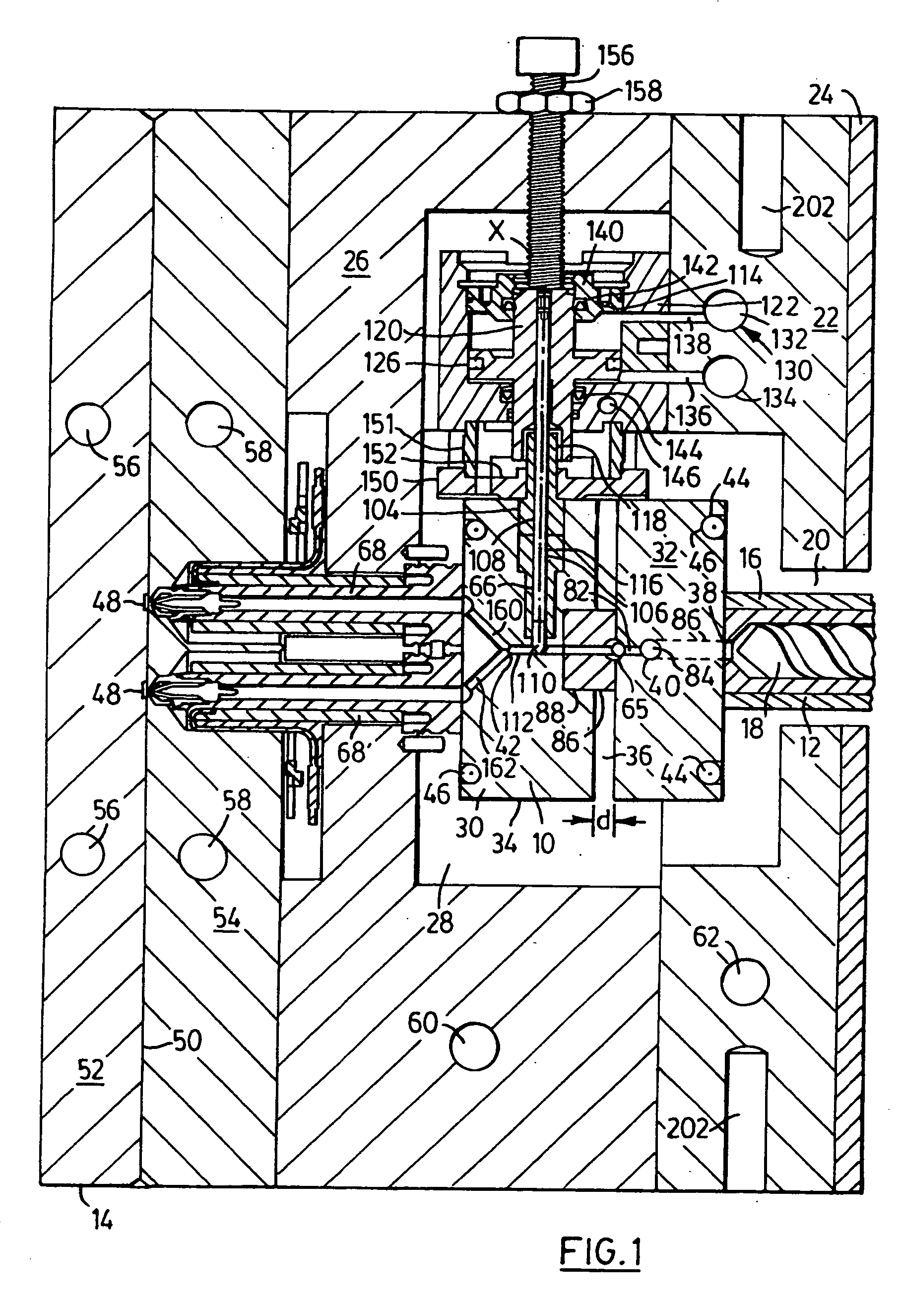
[0028] A hot runner system 10 constructed in accordance with the invention is illustrated in cross-section in FIG. 1 and this system is capable of injecting melted plastics material from a plasticizer unit 12 into an injection mold 14. This hot runner system is particularly useful for molding very small plastic devices and parts, hereinafter referred to as “micro parts”. It will be understood that the plasticizer unit 12 can be of standard construction but is preferably small for such units. The unit 12 can include a barrel 16 and a screw 18 capable of plasticizing the plastic material in a well known manner. The screw is rotated by a motor (not shown) and the barrel is typically heated to the required temperature for the particular plastics material being used by heaters such as electrical heaters. It will be understood that plastic pellets can be fed into the barrel chamber from a feed hopper (not shown). The barrel extends through a suitable opening 20 formed in a clamping plate ...


PUM

PropertyMeasurementUnit
diameteraaaaaaaaaa
diameteraaaaaaaaaa
diameteraaaaaaaaaa

Abstract

A hot runner system for injecting plastics material from a plasticizer unit into an injection mold for molding very small plastic devices, includes a hot runner manifold having an inlet for receiving melted plastics material from the plasticizer unit and a heater for maintaining the manifold at an elevated temperature. A check valve mounted in the manifold allows one way flow of the plastic in the feed conduit. This valve preferably comprises a ball type valve. A metering apparatus includes a cylinder forming an elongate metering chamber and a ram movable therein. An inner end of the chamber opens into one side of the feed conduit downstream of the check valve and the longitudinal axis of the chamber is perpendicular to the longitudinal axis of the conduit where they meet. At least one injector is connected to a downstream end of the feed conduit and it is spaced from the metering apparatus.

Description

BACKGROUND OF THE INVENTION [0001] This invention relates to hot runner systems for injecting plastics materials from a plasticizer unit into an injection mold and, in particular, to hot runner systems suitable for molding very small plastic parts and devices. [0002] Although a number of attempts have been made by various companies to develop systems for efficiently and economically producing small plastic parts such as those that might be used in medical syringes, laboratory ware and surgical equipment, there remains a need to develop improved systems to make micro plastic parts which are not unduly expensive and which are adaptable for the molding of a variety of parts and components. One known system for making small parts is that made by Mold Hotrunner Solutions Inc. of Georgetown, Ontario, Canada, and this uses a multi-nozzle for injecting the plastic material into the mold using several gates arranged on a circle. This arrangement is able to produce a plastic part that consist...

Claims


Application Information

Patent Timeline
Patent Type & Authority Applications(United States)
IPC IPC(8): B29C45/02B29C45/27
CPCB29C45/02B29C2045/0094B29C45/2738B29C45/2701B29C45/2737B29C45/281B29C2045/2848B29C2045/2886
Inventor SCHMIDT, HARALD HANS
Owner WESTFALL ACQUISITION III INC
Why Eureka
Try Eureka