Eccentricity measuring method and eccentricity measuring apparatus

a measuring method and eccentric technology, applied in the direction of measurement devices, instruments, structural/machine measurement, etc., can solve the problems of low measurement accuracy, large loss of light quantity, and inability to accurately measure eccentric quantities, and achieve the effect of accurate measurement of eccentric quantities and low measurement precision

Inactive Publication Date: 2005-06-16
CANON KK
View PDF6 Cites 26 Cited by
  • Summary
  • Abstract
  • Description
  • Claims
  • Application Information

AI Technical Summary

Benefits of technology

[0018] An object of the present invention is to provide an eccentricity measuring apparatus and an eccentricity measuring method which are capable of accurately measuring an eccentric quantity, even in eccentric measurement of a lens system composed of a plurality of lens elements, by analyzing a cause of an unmeasurable surface and a cause of low measurement precision in eccentric measurement performed by a conventional method.

Problems solved by technology

However, when a test lens includes a movable portion as in a zoom lens, accurate eccentric measurement is impossible.
However, measurement light transmits through a half mirror six times, so that a light quantity loss becomes a large problem.
In addition to this, since the number of times in use of a half mirror is small, a light quantity loss is low.
If a reflection image on any of the surfaces cannot be measured, a result of eccentric quantities measured on surfaces located in the back of such a surface becomes inaccurate.
However, when it is intended to actually perform the eccentric measurement by the above-mentioned conventional methods, the state of the reflection image cannot be measured in many cases.
An unmeasurable surface on which the reflection image cannot be measured is caused in some cases.
An eccentric measurement value on a test surface having a large eccentric error includes a large measurement error.
As is apparent from experiments, the test surface having the large eccentric error is likely to become an unmeasurable surface.
However, up to now, the analysis of fundamental causes of the above-mentioned problems and specific measures against the causes are not taken.

Method used


Image

  • Eccentricity measuring method and eccentricity measuring apparatus
  • Eccentricity measuring method and eccentricity measuring apparatus
  • Eccentricity measuring method and eccentricity measuring apparatus

Examples


first embodiment

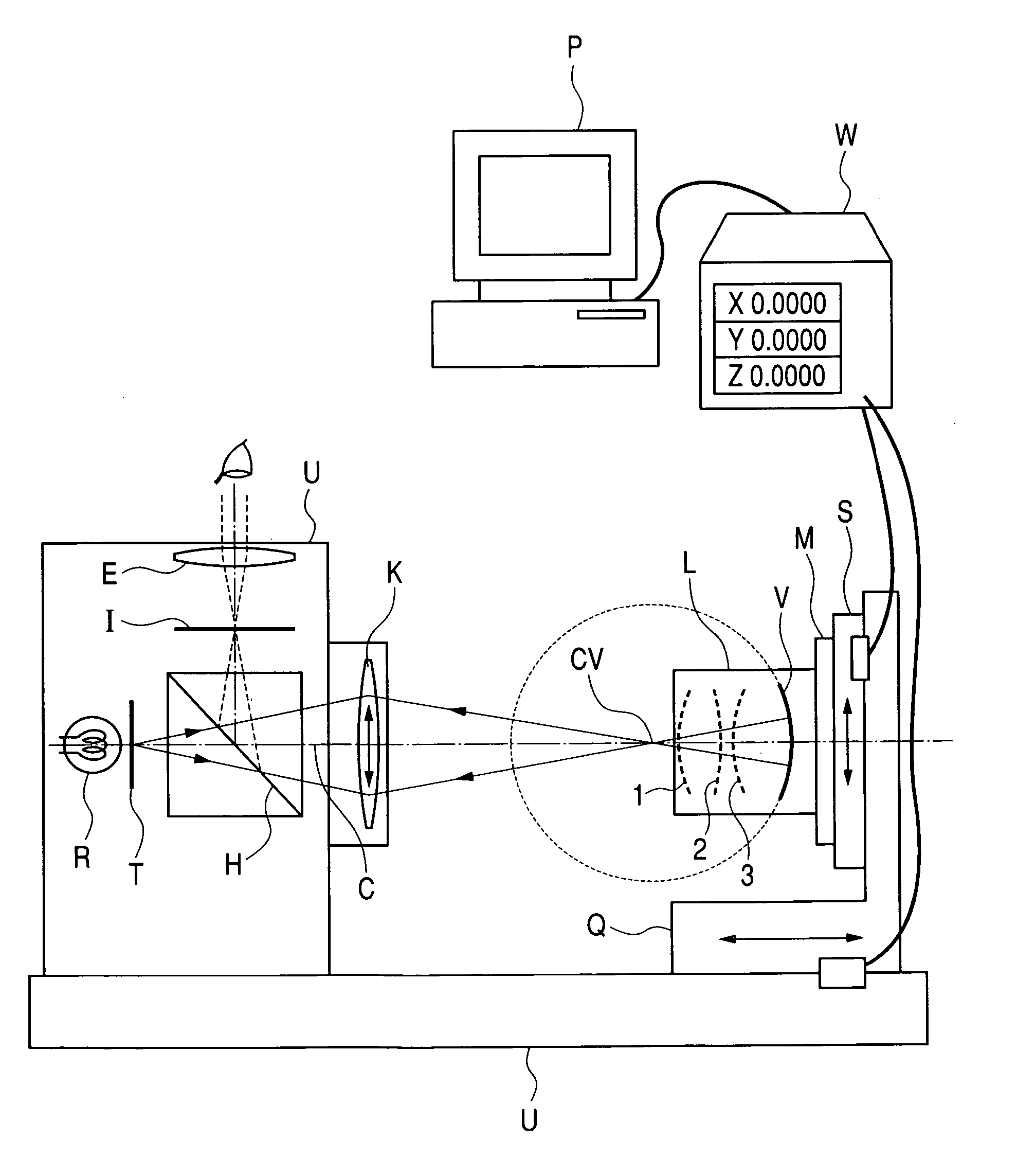
[0054]FIG. 1 is a schematic view showing an eccentricity measuring apparatus according to a first embodiment.

[0055] In FIG. 1, the index chart T illuminated by the illumination light source R is projected to the test lens L by the collimator objective lens K through the half mirror (beam splitter) H. The collimator objective lens K is constructed to be exchangeable. The focal distance of the collimator objective lens K can be varied according to the apparent radius of curvature of the surface to be tested. When the collimator objective lens K is exchanged for another collimator objective lens, a projection image of the index chart T is displaced in some cases before and after the exchange. Thus, the collimator objective lens K has a structure capable of being adjusted in the direction perpendicular to the measurement reference axis (measurement axis) C so as to align the origin of the image of the index chart T with the measurement reference axis C.

[0056] The test lens L is compos...

second embodiment

[0100] Next, an eccentricity measuring apparatus according to the second embodiment will be described with reference to FIG. 5.

[0101] In the second embodiment, instead of using the collimator objective lens K according to the first embodiment, a structure including a collimator lens K1 for forming a parallel light beam and an objective auxiliary lens K2 for imaging the parallel light beam is used. The objective auxiliary lens K2 is constructed to be exchangeable for another objective auxiliary lens or composed of a lens whose focal distance is variable. Therefore, the focal distance of the objective auxiliary lens K2 can be varied. The objective auxiliary lens K2 has a structure capable of being adjusted in the direction perpendicular to the optical axis C such that the projection image of the index chart coincides with the measurement reference axis C when the objective auxiliary lens K2 is exchanged for another objective auxiliary lens. With respect to the index chart T and the i...


PUM


Abstract

A surface to be tested and an optical system for projecting an index to an apparent spherical center position of the surface to be tested are moved relative to each other and an eccentric quantity of the surface to be tested is calculated from an movement quantity. A focal distance of an optical system is changed according to an apparent radius of curvature of each surface to be tested, which is calculated in advance. A reflection image on a surface to be tested, which is to be measured, is determined from the apparent radius of curvature of each surface to be tested, which is calculated in advance. Thus, an eccentric quantity of the entire lens system is accurately measured.

Description

BACKGROUND OF THE INVENTION [0001] 1. Field of the Invention [0002] The present invention relates to an eccentricity measuring method and is suitable to measure eccentricity of a lens system such as a zoom lens, which is composed of a plurality of lens elements and has a movable portion. [0003] 2. Related Background Art [0004] Conventional eccentricity measuring methods are described in detail in “Eccentricity Measurement of Optical System”, Yoshiya Matsui and Masayuki Usui, Optical Technology Contact, Vol. 13, No. 11, pp. 11-20. The following three methods, [0005] (1) a test lens rotation method, [0006] (2) a test lens still East Germany Zeiss method, and [0007] (3) a test lens still image rotator method are introduced. [0008] According to any of those eccentricity measuring methods, an index is projected to the apparent center of curvature of a surface to be tested by an auto-collimation method. An eccentric quantity is calculated from states (deflection and displacement) of a ref...

Claims


Application Information

Patent Timeline
Patent Type & Authority Applications(United States)
IPC IPC(8): G01M11/00G01B9/00G01B11/27G01M11/02
CPCG01M11/0257G01M11/0221G01B11/27G01M11/00
Inventor MURATA, YASUNORI
Owner CANON KK
Why Eureka
Try Eureka