Hot runner nozzle with a tip, a tip surrounding piece and an alignment piece

a technology of hot runner nozzle and surrounding piece, which is applied in the field of injection molding apparatus, can solve the problems of misalignment of the nozzle with respect to the gate, time-consuming process, and build-up of errors

Active Publication Date: 2006-11-21
MOLD MASTERS 2007
View PDF212 Cites 23 Cited by
  • Summary
  • Abstract
  • Description
  • Claims
  • Application Information

AI Technical Summary

Benefits of technology

[0015]In a fourth aspect, the invention relates to a nozzle for an injection molding machine. The injection molding machine has a mold block that defines at least one mold cavity with a gate leading thereto. The nozzle has a nozzle body, a tip, a tip surrounding piece and an alignment piece. The tip is mounted with respect to the nozzle body, such as by being mounted directly to the nozzle body, or by being mounted to another component that is connected to the nozzle body. The tip has an upstream end and a downstream end. The tip has at least one upstream alignment surface that cooperates with an alignment surface on another component of the nozzle, such as the nozzle body, to align the tip with respect to the nozzle body upstream from the downst...

Problems solved by technology

Several factors generally cause the nozzle to be misaligned with respect to the gate.
One such factor is a build-up of error due to tolerances in the manufacturing of the mold plate in which the gates are positioned, the manifold plate to which the nozzles are attached, and the nozzles themselves.
This can be a time-consuming process.
Furthermore, other problems exist with the alignment of the valve pin.
If the torpedo is even sli...

Method used


Image

  • Hot runner nozzle with a tip, a tip surrounding piece and an alignment piece
  • Hot runner nozzle with a tip, a tip surrounding piece and an alignment piece
  • Hot runner nozzle with a tip, a tip surrounding piece and an alignment piece

Examples


Embodiment Construction

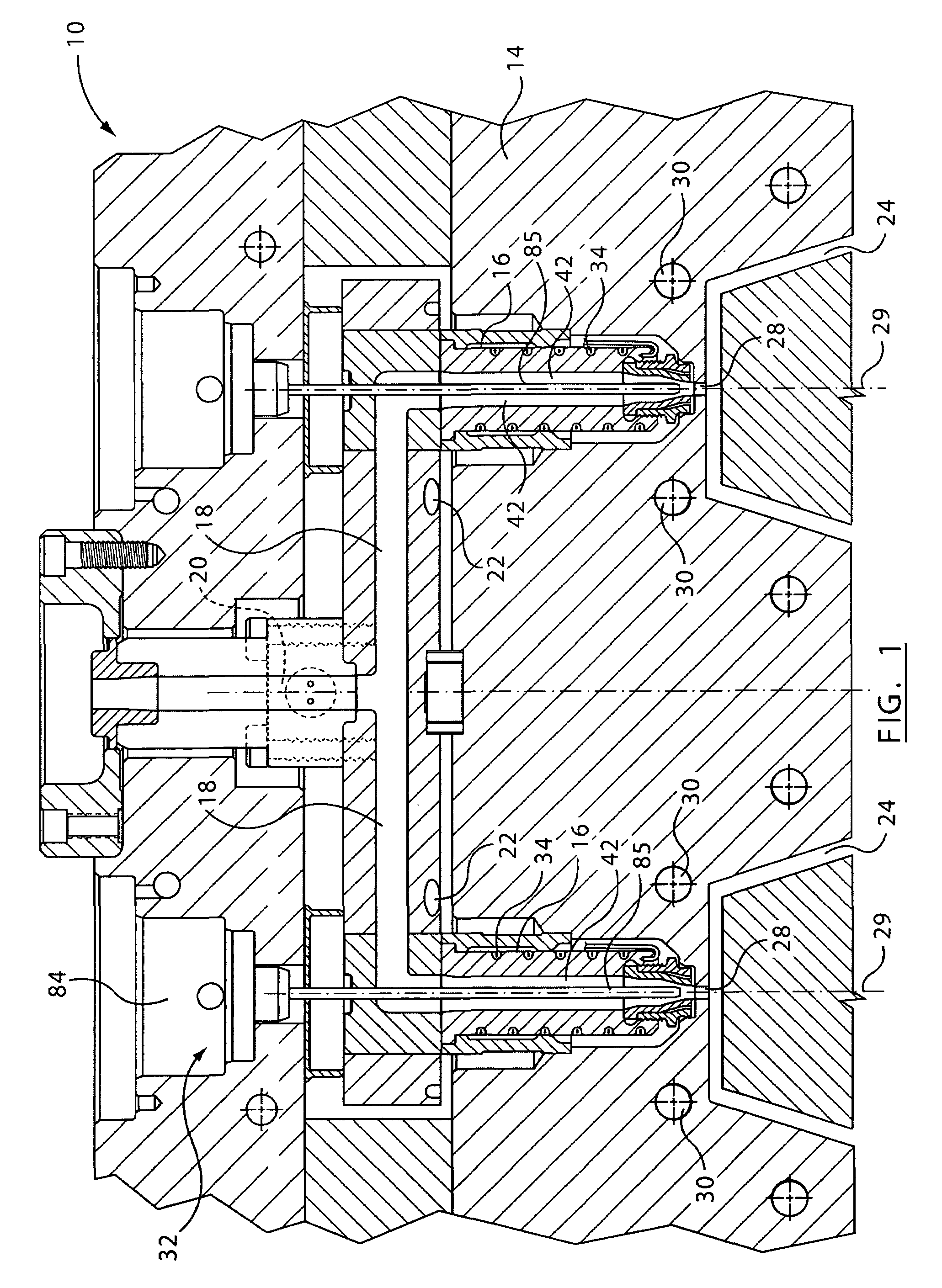
[0029]Reference is made to FIG. 1, which shows an injection molding apparatus 10, which includes a manifold 12, a mold component 14 and a plurality of nozzles 16 in accordance with a first embodiment of the present invention.

[0030]The manifold 12 includes a plurality of runners 18, which transfer melt from a main runner inlet 20 to the nozzles 16. The manifold 12 may be heated by a heater 22.

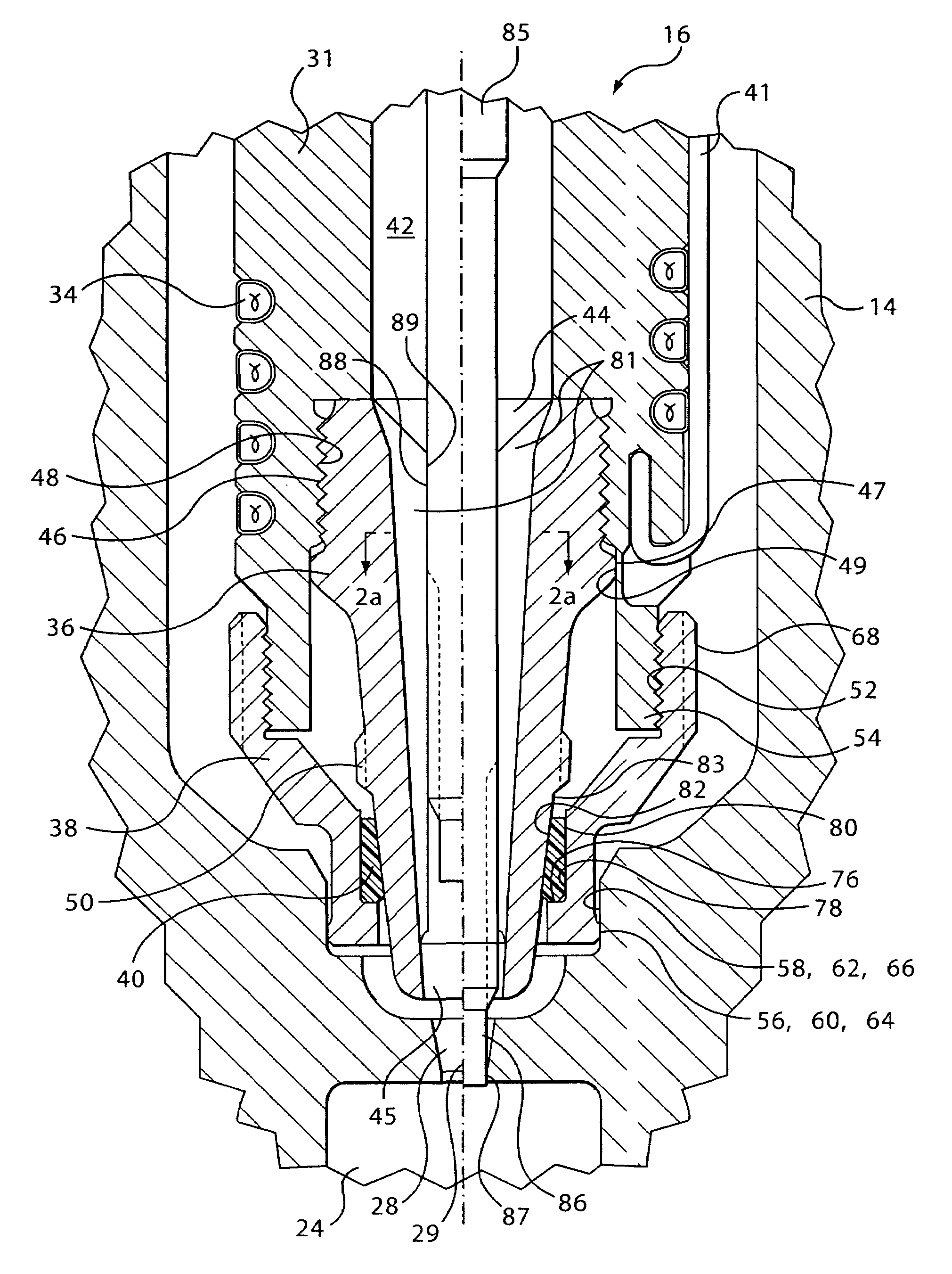
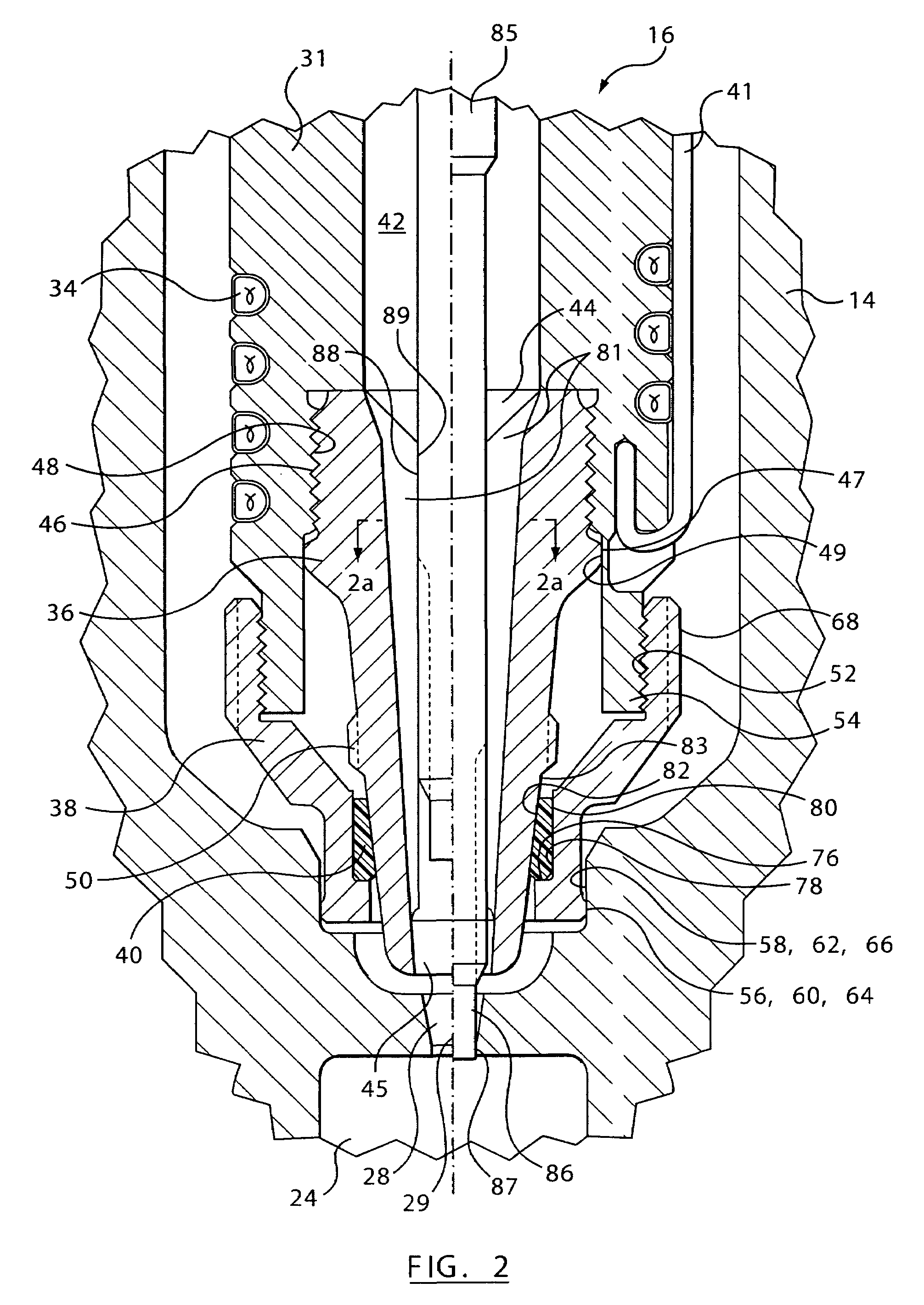
[0031]The mold component 14 is made up of a plurality of mold plates, which together define a plurality of mold cavities 24. A gate 28 into each mold cavity 24 is defined in the mold component 14. Each gate 28 is positioned downstream from one of the nozzles 16. Each gate 28 defines an axis 29.

[0032]A plurality of cooling channels 30 may be included in the mold component 14. The cooling channels 30 transport a cooling fluid throughout the mold component 14 to cool and solidify melt in the mold cavities 24. It is alternatively possible that the mold component 14 be cooled by any other means known...


PUM

PropertyMeasurementUnit
Melting pointaaaaaaaaaa
Heataaaaaaaaaa
Thermal conductivityaaaaaaaaaa

Abstract

A nozzle for an injection molding apparatus is provided. The injection molding apparatus includes a manifold and a mold component. The manifold has at least one runner therein that is downstream from a melt source. The mold component defines at least one mold cavity and defining a gate into each mold cavity. The gate defines an axis. The mold component has a mold component alignment surface thereon. The nozzle includes a nozzle body, a tip, a tip surrounding piece and an alignment piece. The nozzle body defines a nozzle body melt passage, which is adapted to be in fluid communication and downstream from the at least one runner. The tip is removably connected to the nozzle body. The tip defines a tip melt passage therethrough. The tip melt passage is downstream from and in fluid communication with the nozzle body melt passage, and is upstream from and in fluid communication with the gate. The tip surrounding piece is removably connected with respect to the nozzle body. The alignment piece is positioned between the tip and the tip surrounding piece. The tip contacts the alignment piece to align the tip with respect to the alignment piece. The alignment piece contacts the tip surrounding piece to align the alignment piece with respect to the tip surrounding piece. The tip surrounding piece is adapted to contact the mold component to align the tip surrounding piece with respect to the gate, so that the tip is aligned with respect to the gate. The contact between the tip, the alignment piece, the tip surrounding piece and the mold component is adapted to be axially proximate the gate.

Description

[0001]This application claims the benefit of U.S. Provisional Application No. 60 / 427,926, filed on Nov. 21, 2002.FIELD OF THE INVENTION[0002]This invention relates to an injection molding apparatus, and more particularly to a hot runner nozzle for an injection molding apparatus.BACKGROUND OF THE INVENTION[0003]In a hot runner injection molding apparatus, melt is transferred from a melt source through a system of runners, through a nozzle and into a mold cavity through a gate. When the mold cavity is opened for the ejection of the molded part, it is important to prevent leakage of hot melt from the nozzle through the gate.[0004]A valve pin is commonly used to seal the gate into the mold cavity prior to opening the mold cavity. The valve pin is positioned in the nozzle, and is movable into and out of the gate to control the flow of melt therethrough.[0005]Proper alignment of the valve pin with respect to the gate can impact on the longevity of both the valve pin and the gate, and the ...

Claims


Application Information

Patent Timeline
IPC IPC(8): B29C45/23B22D17/22B29C45/27B29C45/28
CPCB22D17/2272B29C45/278B29C45/2806B29C2045/2759B29C2045/2766B29C2045/2785
Inventor BABIN, DENISCOLONICO, GINO
Owner MOLD MASTERS 2007
Why Eureka
Try Eureka