Perforating gun assembly and methods of use

a perforating gun and assembly technology, applied in the direction of fluid removal, wellbore/well accessories, construction, etc., can solve the problems of hammering the design objective of limited entry, adverse effect on the production flow geometry in a radial direction around the wellbore, etc., to improve the perforation connectivity and/or fracture initiation, and improve the placement control

Active Publication Date: 2018-08-02
DELPHIAN BALLISTICS
View PDF11 Cites 6 Cited by
  • Summary
  • Abstract
  • Description
  • Claims
  • Application Information

AI Technical Summary

Benefits of technology

[0012]It is amongst the aims and objects of the invention to provide a perforating gun assembly and a method of use in perforating and/or hydraulic fracturing applications which obviates or mitigates drawbacks and deficiencies of previously proposed apparatus and methods.
[0013]It is amongst the aims and objects of the invention to provide a perforating gun assembly and a method of use

Problems solved by technology

In longer perforation intervals, fracture tortuosity and multiple fracture events, both of which hamper the design objective of Limited Entry, can be prevalent.
Convergent charge configurations can go some way to achieving Limited Entry, but disadvantages of convergent charge configurations of the types described in U.S. Pat. No

Method used


Image

  • Perforating gun assembly and methods of use
  • Perforating gun assembly and methods of use
  • Perforating gun assembly and methods of use

Examples


Embodiment Construction

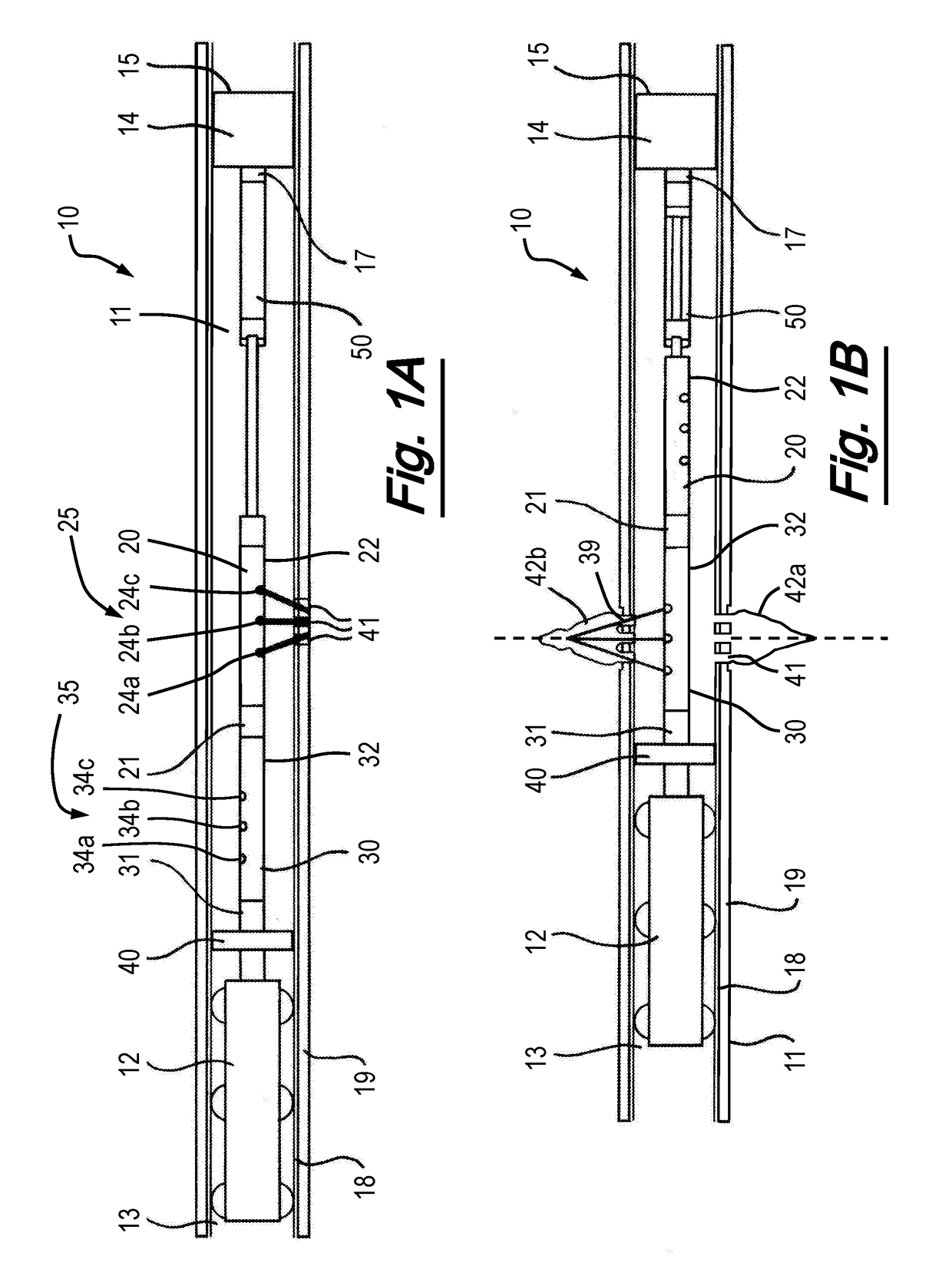
[0110]Referring firstly to FIGS. 1A and 1B, there is shown schematically a perforating gun assembly, generally depicted at 10, located in a cased wellbore 11. FIG. 1A shows the assembly 10 in an initial detonation position, and FIG. 1B shows the perforating gun assembly of FIG. 1A in a second detonation position, as will be described below. It is an aim of the invention to provide a perforating gun assembly for hydraulic fracturing applications, and the following embodiments of the invention will be described in that context. However, the invention has application to alternative reservoir treatment operations, and its benefits may also arise where the invention is applied to injection of other fluids, such as in water and or gas flood operations, in which breakdown (fracturing) of the formation is often (but not necessarily) a consequence of such operations.

[0111]The assembly 10 is designed to be deployed on a wireline or other flexible conveyance (not shown) with the assistance of ...


PUM


Abstract

In one aspect, the method comprises providing a perforating gun assembly having a first group of shaped charges on first longitudinal portion of the assembly and a second group of shaped charges on a second longitudinal portion of the assembly. The orientations of the first and second groups are rotationally offset from one another around a longitudinal axis of the perforating gun assembly. The method comprises locating the perforating gun assembly in a wellbore with the first group of shaped charges adjacent a wall of the wellbore at a perforation location, and detonating the shaped charges to form a first perforation channel in the wellbore with a defined first fracture initiation point. The perforating gun assembly is translated in the wellbore to locate the second group of shaped charges orientedtowards a defined second fracture initiation point, at a desired axial position with respect tothe first fracture initiation point.

Description

[0001]The present invention relates to a perforating gun assembly and a method of use in perforating and / or hydraulic fracturing applications. In particular, but not exclusively, the invention relates to a perforating gun assembly comprising convergent shaped charge orientations and a method of use in a perforating operation prior to fracture initiation. Aspects of the invention relate to hydraulic fracturing methods.BACKGROUND TO THE INVENTION[0002]In the hydrocarbon exploration and production industry, it is common to use perforating guns to form fluid communication paths (“perforations”) in a subterranean formation between a hydrocarbon reservoir and a drilled wellbore that traverses the reservoir. The communication paths enable the inflow of production fluids into the wellbore, and enable the delivery of stimulation fluids to the formation, for example during hydraulic fracturing operations. Typically perforating methods are applied to cased hole wellbores, which include a casin...

Claims


Application Information

Patent Timeline
IPC IPC(8): E21B43/117E21B43/26
CPCE21B43/117E21B43/26E21B43/119E21B23/001E21B43/118
Inventor ALLISON, SIMON DOUGLAS EARDLY
Owner DELPHIAN BALLISTICS
Why Eureka
Try Eureka