Method of achieving jet separation of an un-separated flow in a divergent nozzle body of a rocket engine

a rocket engine and jet separation technology, applied in the direction of machines/engines, vessel construction, marine propulsion, etc., can solve the problems of jet separation, difficult to implement active secondary injection, and unstable position, and achieve the effect of avoiding such instability

Inactive Publication Date: 2006-02-14
EUROPEAN SPACE AGENCY
View PDF15 Cites 9 Cited by
  • Summary
  • Abstract
  • Description
  • Claims
  • Application Information

AI Technical Summary

Benefits of technology

[0025]An object of the invention is to propose a separation control system, especially through secondary injection which avoids such instability.

Problems solved by technology

The known techniques of secondary injection, which involve jet separation exhibiting axial symmetry, that is to say which is invariant about any rotation about the axis of the nozzle, exhibit the following problems:active secondary injection is difficult to implement, given that the mass flux which is required for effective generation of axial symmetric jet separation is high;passive secondary injection which implements ventilation of the nozzle is operational only within a limited range of differential pressure, which implies that in order to obtain a nozzle which operates at all altitudes, its porosity must be continuously variable as a function of external pressure and of the operational parameters of the engine, this being hardly compatible with the nozzle construction constraints.
One of the drawbacks of secondary injections with axial symmetry, such as for example that described in the aforesaid American patent, is that under certain engine operating conditions, the jet separation commences at a random point on the injection ring, and whose position, which depends on the upstream disturbances, is unstable.

Method used


Image

  • Method of achieving jet separation of an un-separated flow in a divergent nozzle body of a rocket engine
  • Method of achieving jet separation of an un-separated flow in a divergent nozzle body of a rocket engine

Examples


Embodiment Construction

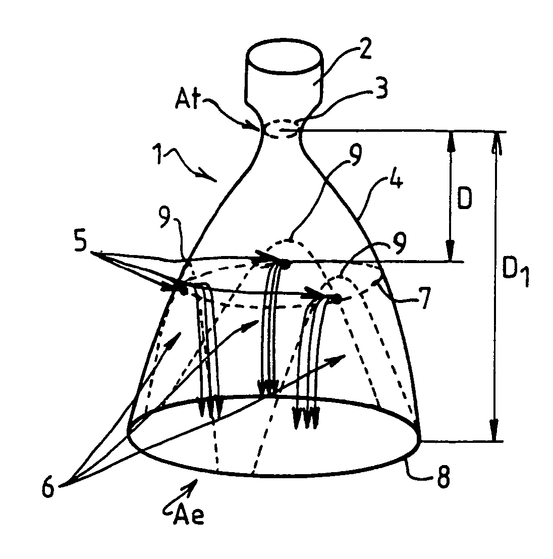
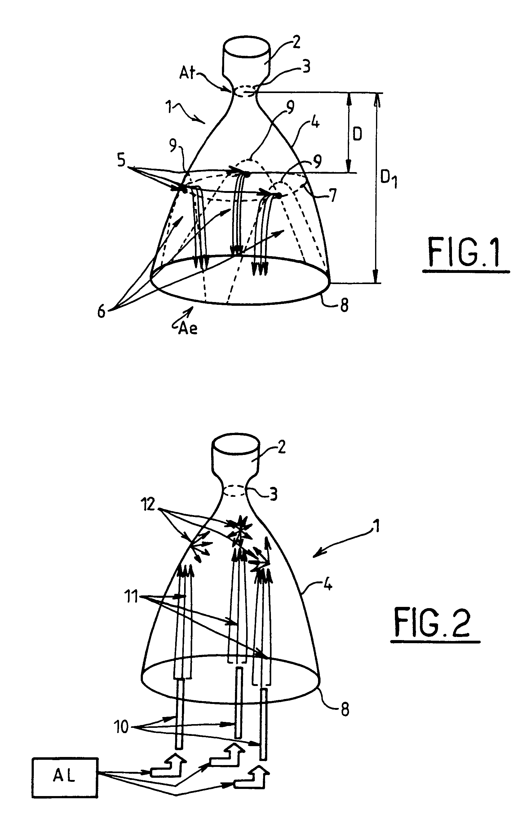
[0044]As shown in FIG. 1, a nozzle, designated by the general label 1, exhibits a combustion chamber 2, a throat 3, and a divergent nozzle body 4 which terminates in an exit cross section 8.

[0045]Over the perimeter of the divergent portion 4 of the nozzle, and in a cross section 7 situated in a plane, perpendicular to the axis of the nozzle, where the static pressure P of the jet is substantially greater than the nozzle separation pressure Psep, are arranged injection orifices 5 able to direct radially inward a jet of a fluid, for example the combustion gases originating from the turbopumps of the engine.

[0046]The flow separation which is generated by these orifices 5, does not exhibit axial symmetry, but on the contrary it is three-dimensional. This is because each of the injection points 5, represented here as three in number and distributed uniformly at 120° around the contour of the body 4 of the nozzle, induces a region of separation 6 of the stream exiting the nozzle. Owing to...


PUM


Abstract

The invention relates to a rocket engine nozzle comprising a system for controlling jet separation of the flow in the nozzle, wherein said control system exhibits a plurality of separation triggering elements (5, 10) arranged in such a way as to generate, from mutually spaced initiation points (9), distinct zones (6) of jet separation, so as to form a three-dimensional separation of the flow.
The flow control system can exhibit at least two triggering elements (5, 10).

Description

CROSS-REFERENCE TO RELATED APPLICATIONS[0001]This is a divisional of parent application Ser. No. 09 / 534,196 filed Mar. 24, 2000, now abandoned the disclosure of which is incorporated herein.BACKGROUND OF THE INVENTION[0002]1. Field of the Invention[0003]The subject of the present invention is a rocket engine nozzle, exhibiting a jet separation control system, for example a device for injecting fluid through a wall of the nozzle, so as to induce jet separation in the gases ejected by the nozzle.[0004]An important point in the design of a launcher is the optimization of the performance of its engines. In particular, the nozzle must be designed so as to yield a maximum thrust coefficient compatible with the limits imposed by the other constraints.[0005]The thrust coefficient C of a nozzle is an increasing function of the ratio of the exit area Ae of the nozzle to the area At of the throat of the nozzle.[0006]For an upper stage, which is ignited outside the atmosphere, the static pressu...

Claims


Application Information

Patent Timeline
Patent Type & Authority Patents(United States)
IPC IPC(8): F02K1/28F02K9/82F02K9/97
CPCF02K9/82F02K9/97F05D2250/324F05D2250/323
Inventor DUJARRIC, CHRISTIAN FRANCOIS MICHEL
Owner EUROPEAN SPACE AGENCY
Why Eureka
Try Eureka