Turbine driven electric power production system and a method for control thereof

a technology of electric power production system and turbine, which is applied in the direction of fluid coupling, non-mechanical valve, stove or range, etc., can solve the problems of compromising the steady-state accuracy of the turbine, unable to provide an acceptable dynamic response, and unable to achieve steady-state accuracy, etc., to achieve the effect of improving the accuracy of the operating point, reducing the rate of variation in the hydraulic pressure, and maximizing efficiency

Inactive Publication Date: 2011-01-04
CHAPDRIVE AS
View PDF44 Cites 62 Cited by
  • Summary
  • Abstract
  • Description
  • Claims
  • Application Information

AI Technical Summary

Benefits of technology

There are some advantages of measuring the turbine rotational speed and using this as an input to a control system according to the invention when compared to the system using pressure measurements for controlling the generator speed such as described in U.S. Pat. No. 4,503,673. The advantages include improved accuracy of the operating point for maximum efficiency. This is because of the low rate of variation in the hydraulic pressure with changes in turbine speed, for a given wind speed, which could cause uncertainty in its operation. It is also likely that the graphical relationship is concave upwards which could worsen this problem. Using turbine speed control the speed that creates maximum turbine efficiency can be more precisely defined. As a result of the above, and also because of the way in which the hydraulic pressure arises in the system, it is likely that there would be problems in providing an acceptable dynamic response for a pressure control system. In this event and to avoid instability, the value of system controller gain would have to be set at a level that would further compromise its steady-state accuracy.

Problems solved by technology

This is because of the low rate of variation in the hydraulic pressure with changes in turbine speed, for a given wind speed, which could cause uncertainty in its operation.
It is also likely that the graphical relationship is concave upwards which could worsen this problem.
As a result of the above, and also because of the way in which the hydraulic pressure arises in the system, it is likely that there would be problems in providing an acceptable dynamic response for a pressure control system.
In this event and to avoid instability, the value of system controller gain would have to be set at a level that would further compromise its steady-state accuracy.

Method used


Image

  • Turbine driven electric power production system and a method for control thereof
  • Turbine driven electric power production system and a method for control thereof
  • Turbine driven electric power production system and a method for control thereof

Examples


Embodiment Construction

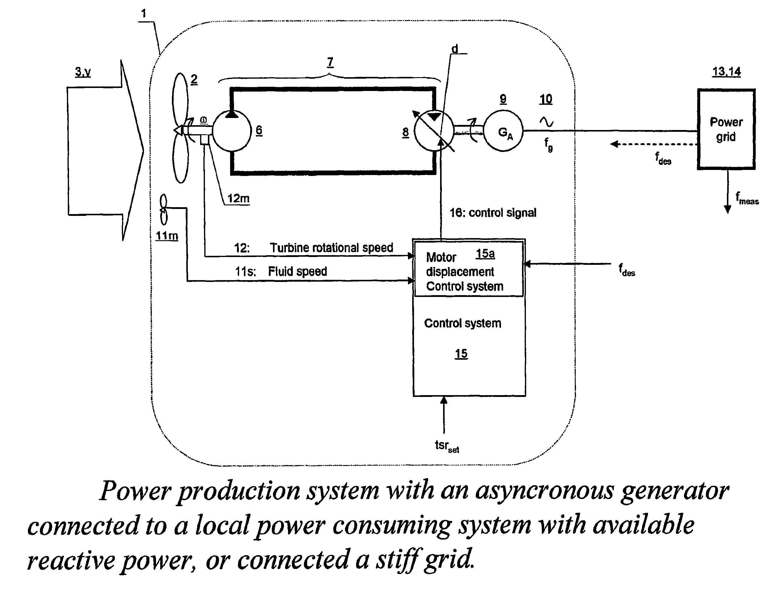
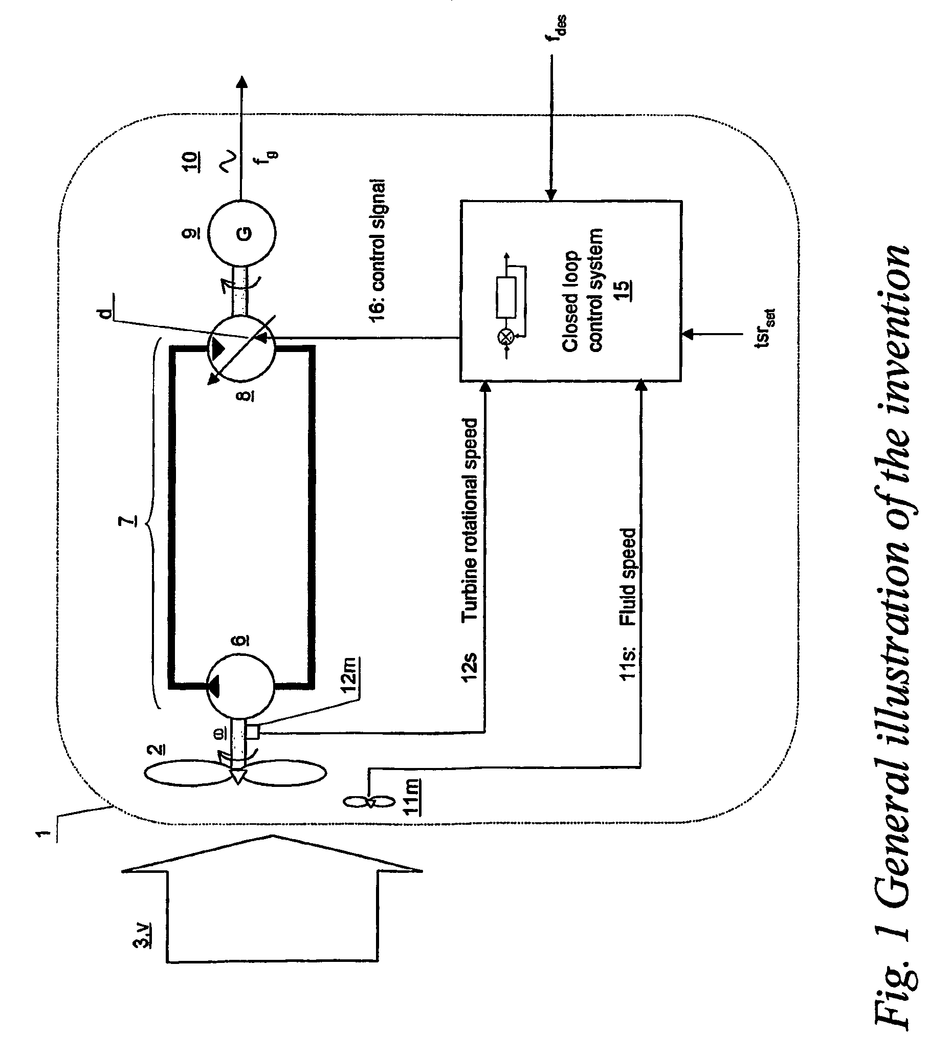
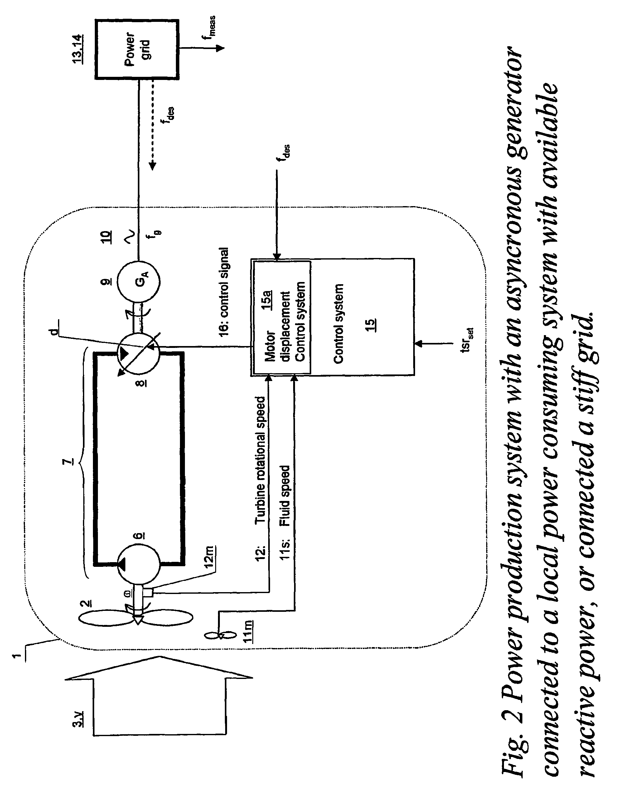
The invention comprises a turbine driven electric power production system (1). The turbine (2) is arranged for being driven by a fluid (3), the fluid having a fluid speed (v) varying in time, such as is the case for a wind turbine or a water turbine. In the below specification, only examples comprising wind turbines are discussed, however, as will be evident to a person skilled in the art, the invention equally applies to water driven turbines. The turbine (2) is connected to run a hydrostatic displacement pump (6) further connected to a hydrostatic displacement motor (8) as part of a hydrostatic transmission system (7), please see FIG. 1. The hydrostatic system may be a closed loop hydrostatic system or an open loop hydrostatic system. The hydrostatic motor (8) is arranged to transfer the rotational moment by being connected to the rotation axle of an electrical generator (9) supplying AC power (10). The AC power is usually required to be produced at a frequency (fg) stabilised nea...


PUM


Abstract

A turbine (2) driven electric power production system (1),—said turbine (2) arranged for being driven by a fluid (3) having a fluid speed (v) varying in time,—said turbine (2) connected to a hydrostatic displacement pump (6) further connected to a hydrostatic displacement motor (8) as part of a closed loop hydrostatic transmission system (7),—said motor (8) arranged for driving an electrical generator (9) supplying AC power (10) at a frequency (fg) near a given desired frequency (fdes), characterized by a closed loop system arranged for controlling a volumetric displacement (13) of the hydrostatic motor (8), comprising—a fluid speed meter (11m) arranged for producing a speed signal (11s) representing a speed (v) of said fluid (3), and—a rotational speed meter (12m) arranged for providing a rotational speed signal (12s) representing a rotational speed measurement (ω) of said turbine (2), —a motor displacement control system (15) for continuously receiving said speed signal (11s) and said rotational speed signal (12s) and arranged for calculating a control signal (16), —a volumetric displacement control actuator (17) on said hydrostatic motor, arranged for receiving said control signal (16) for continuously adjusting a volumetric displacement (d) of said hydrostatic motor (8) for maintaining a set turbine tip speed ratio (tsrset) and thereby providing an improved power efficiency of the power production system (1) during fluctuations in said fluid speed (v).

Description

TECHNICAL FIELDThe invention relates to a turbine driven electric power production system and a system for control thereof. More specifically, the invention relates to an electric power production system in which a turbine is driven by a fluid of which the fluid speed is varying in time, the turbine driving a hydrostatic displacement pump connected to a hydrostatic displacement motor in a hydrostatic transmission system, the motor further driving an electrical generator supplying AC power at a frequency near a given desired frequency. Fluid speed measurements, turbine speed measurements and hydrostatic motor or generator speed measurements may be used as input to a motor displacement control system for calculating a control signal, for controlling a volumetric displacement of the hydrostatic motor.BACKGROUND ARTConventionally the power from wind turbine systems is transferred mechanically, either directly or by a rotational speed changing gearbox to a generator. The generator can be...

Claims


Application Information

Patent Timeline
Patent Type & Authority Patents(United States)
IPC IPC(8): F03B13/00H02P9/04F03B13/10F03D9/00
CPCF03D7/02F03D7/0224F03D7/0284F03D7/043F03D11/02F05B2210/16F05B2260/406F05B2260/74F05B2270/101F05B2270/104F05B2270/327F05B2270/337F16H61/465F16H61/47Y02E10/722Y02E10/723F03D15/00F03D80/70F03D9/255Y02E10/72
Inventor CHAPPLE, PETERDAHLHAUG, OLE GUNNARHAARBERG, PER OLAV
Owner CHAPDRIVE AS
Why Eureka
Try Eureka