Selectable output well perforator and method for producing variable hole profiles
a perforator and variable technology, applied in the field of wells, can solve the problems of clogging of small diameter holes (as produced by conventional shaped charges), unable to produce one jet profile per design, and single perforator lacks the ability to handle varying well and rock conditions
- Summary
- Abstract
- Description
- Claims
- Application Information
AI Technical Summary
Problems solved by technology
Method used
Image
Examples
case 12
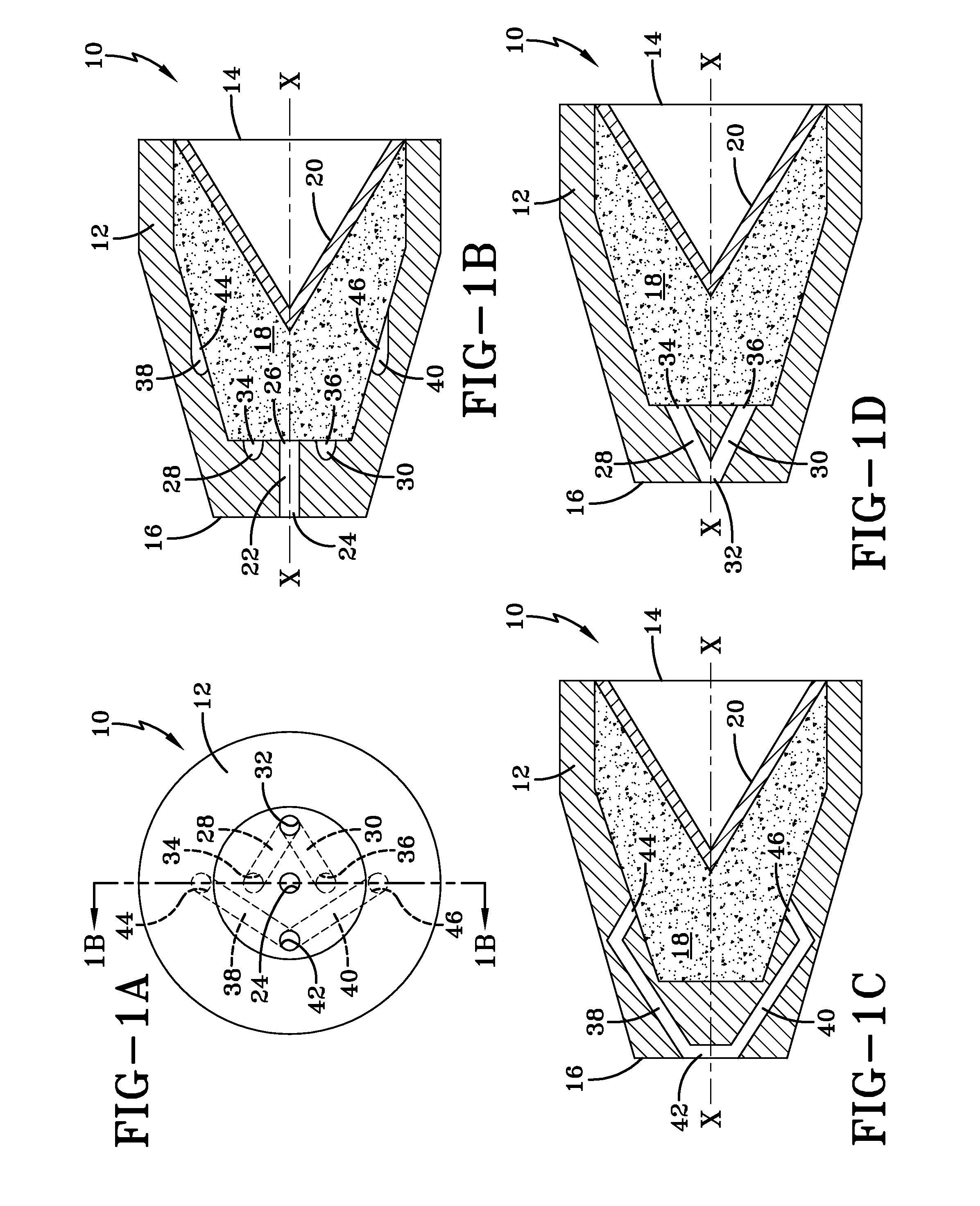
[0035]Case 12 includes a first channel 22 extending from an opening 24 on the rear end of the case along the longitudinal axis X-X to an opening 26 in the interior of the case adjacent the explosive material. A pair of second channels 28, 30 have a common opening 32 on the rear end of the case. The common opening 32 is a different opening than the opening 24 for the first channel 22. The pair of second channels 28, 30 end in a pair of diametrically opposed openings 34, 36 in the interior of the case adjacent the explosive material. The pair of openings 34, 36 are disposed on opposite sides of the opening 26 of the first channel 22. Preferably, the pair of openings 34, 36 are about a same distance from the interior case opening 26 for the first channel 22. More preferably, the pair of openings 34, 36 and the interior case opening 26 for the first channel are substantially collinear.
[0036]Shaped charge 10 further comprises a pair of third channels 38, 40. The pair of third channels 38...
case 52
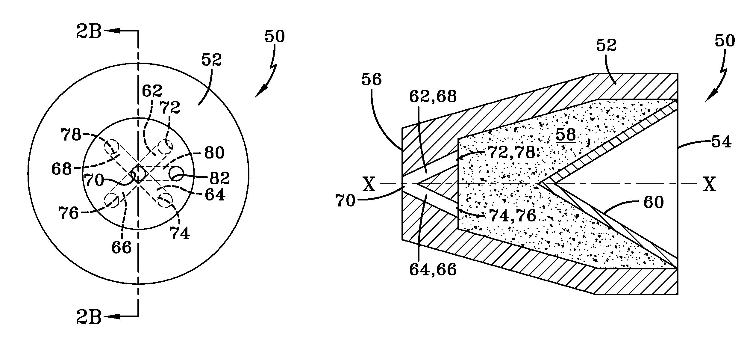
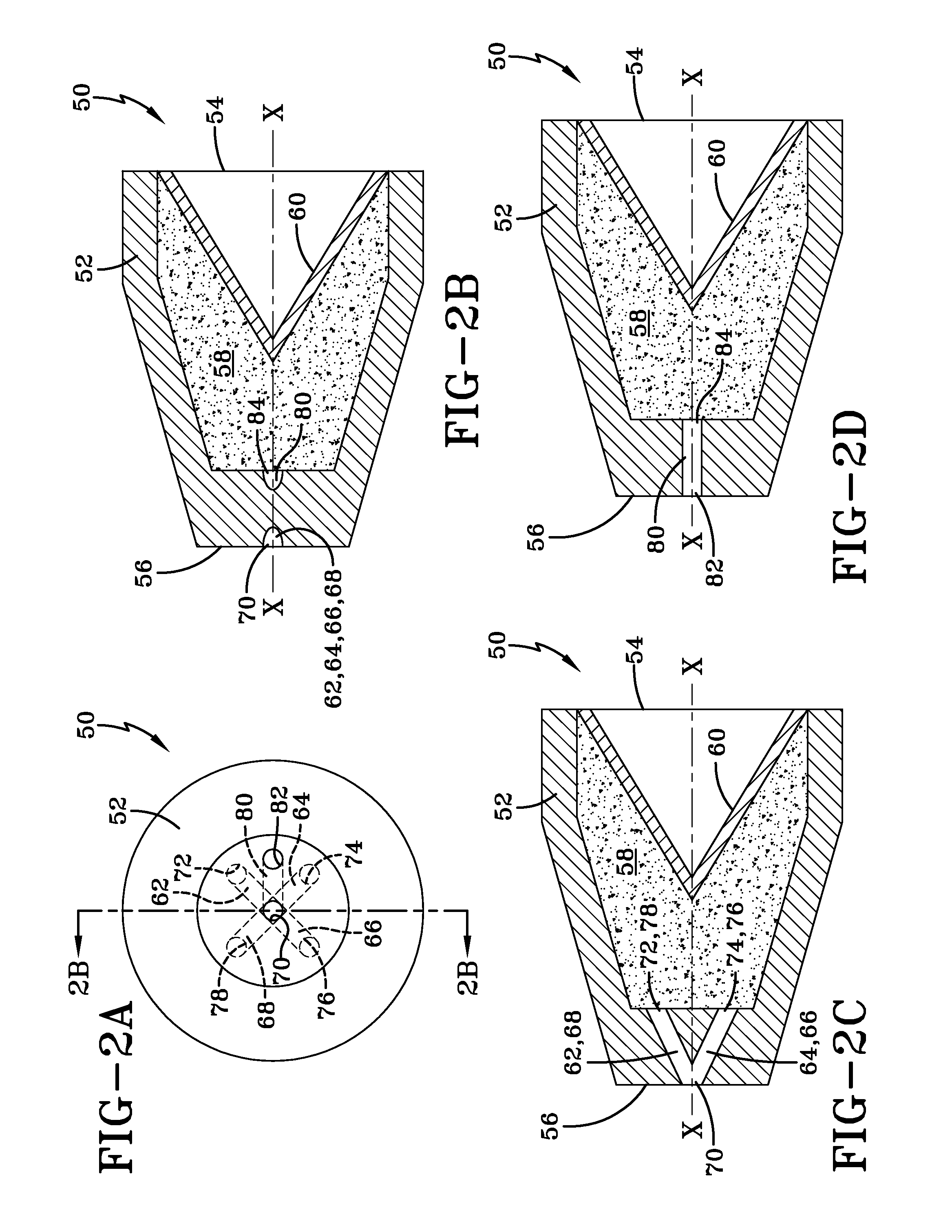
[0038]Case 52 includes four channels 62, 64, 66, 68 extending from a common opening 70 on the rear end of the case to four diametrically opposed openings 72, 74, 76, 78 in the interior of the case adjacent the explosive material. The common opening 70 on the rear end of the case may be centered on the longitudinal axis X-X. The four openings 72-78 in the interior of the case are circumferentially spaced about 90 degrees apart and are equidistant from the longitudinal axis X-X.
[0039]Case 52 further comprises a fifth channel 80 extending from an opening 82 on the rear end of the case to an opening 84 in the interior of the case adjacent the explosive material. The opening 82 on the rear end of the case is a different opening than the common opening 70 for the four channels 62-68. The opening 84 in the interior of the case is centered on the longitudinal axis X-X.
[0040]In shaped charges 10 and 50, each set of channels begins at a common initiation point on the rear end of the case and ...
case 92
[0043]Case 92 includes a first channel 102 extending from an opening 104 on the rear end of the case 92 along the longitudinal axis X-X to an opening 106 in the interior of the case adjacent the explosive material. A pair of second channels 108, 110 extend from a pair of openings 112, 114 on the rear end of the case to a pair of diametrically opposed openings 116, 118 in the interior of the case adjacent the explosive material. The pair of openings 116, 118 are disposed on opposite sides of the opening 106.
[0044]Shaped charge 90 further comprises a pair of third channels 120, 122 extending from a pair of openings 124, 126 on the rear end of the case to a pair of diametrically opposed openings 128, 130 in the interior of the case adjacent the explosive material. The pair of openings 128, 130 are disposed on opposite sides of the opening 106, radially outward from the pair of openings 116, 118 and axially forward of the openings 116, 118.
[0045]Additional pairs of channels may be added...
PUM
 Abstract
Description
Claims
Application Information
 - R&D
- Intellectual Property
- Life Sciences
- Materials
- Tech Scout
- Unparalleled Data Quality
- Higher Quality Content
- 60% Fewer Hallucinations
Browse by: Latest US Patents, China's latest patents, Technical Efficacy Thesaurus, Application Domain, Technology Topic, Popular Technical Reports.
© 2025 PatSnap. All rights reserved.Legal|Privacy policy|Modern Slavery Act Transparency Statement|Sitemap|About US| Contact US: help@patsnap.com


