Micro mirror device and projector employing the same

a technology of mirror device and projector, which is applied in the direction of projector, television system, instrument, etc., can solve the problems of color breakage, noise, and inability to stably activate, and achieve the limitation of reducing light to beam siz

Inactive Publication Date: 2005-01-18
SAMSUNG ELECTRONICS CO LTD
View PDF4 Cites 7 Cited by
  • Summary
  • Abstract
  • Description
  • Claims
  • Application Information

AI Technical Summary

Benefits of technology

Also, the micro mirror units can secure the reflection area of incident light to align the micro mirror units very closely to one another.

Problems solved by technology

However, because the color wheel 125 rotates at high speed, it makes noise and is not actuated stably.
Further, due to the mechanical limitation of the color wheel 125, the color wheel 125 does not rotate beyond a predetermined speed, which would cause color breakup.
However, there is a limitation in reducing light to beam size.
In addition, the color wheel 125 is very expensive, thereby increasing manufacturing cost.

Method used


Image

  • Micro mirror device and projector employing the same
  • Micro mirror device and projector employing the same
  • Micro mirror device and projector employing the same

Examples


Embodiment Construction

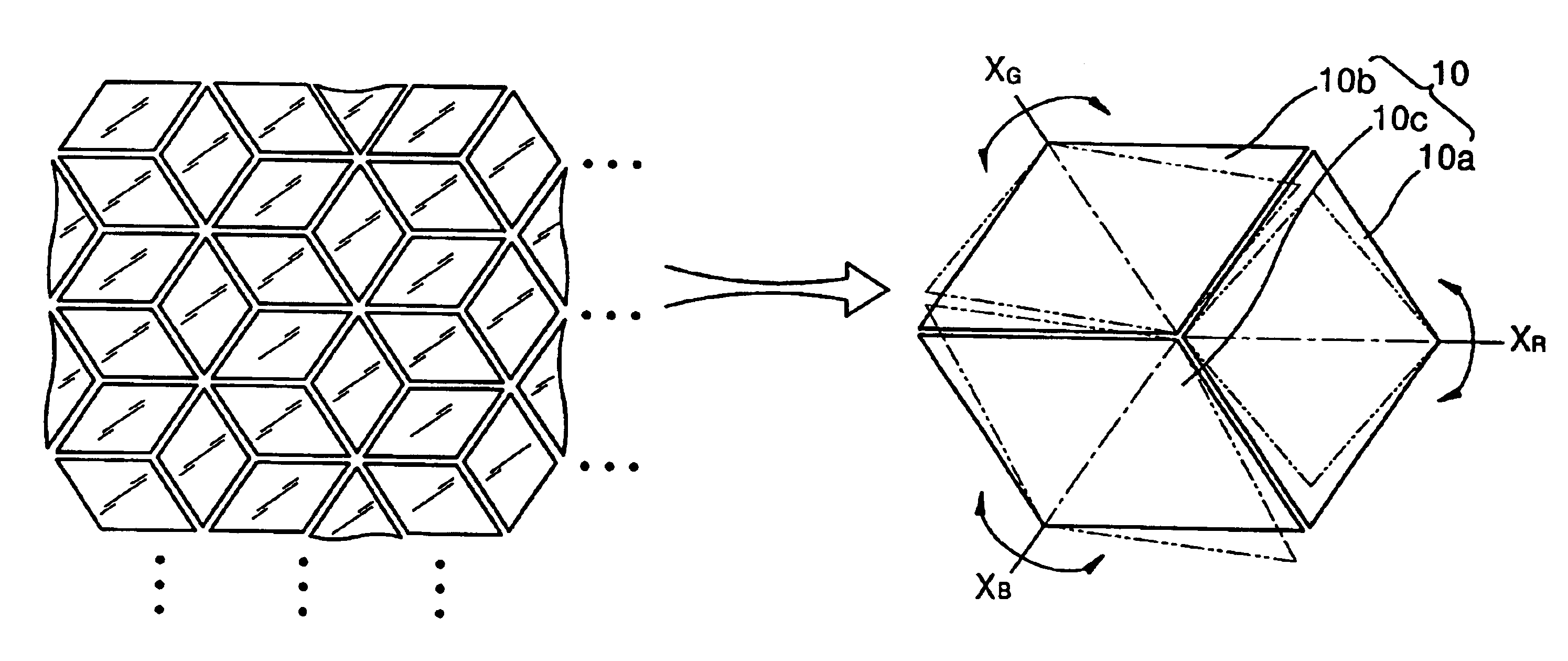
Referring to FIG. 3, a micro mirror device according to a preferred embodiment of the present invention includes a plurality of micro mirror units 10 that are each composed of a plurality of micro mirrors whose driving axes are positioned at different angles. The driving axes of the plurality of micro mirrors constituting the micro mirror unit 10 are positioned in different directions, and thus, the direction of beams, which are output from the micro mirror unit 10, become different from one another when each micro mirror slants with regard to these driving axes. The micro mirror units 10 includes, for instance, first through third micro mirrors 10a through 10c whose first through third driving axes XR, XG, and XB are positioned by 120 degree from one another.

Preferably, the first through third micro mirrors 10a through 10c are symmetrical with regard to each of the driving axes XR, XG, XB, and positioned very closely to neighboring micro mirrors so as to secure the maximum reflecti...


PUM


Abstract

Provided are a micro mirror device capable of realizing color images without a color wheel by selectively reflecting color beams using a plurality of micro mirrors whose driving axes are positioned in different directions, and a projector employing the same. The micro mirror device can individually control a plurality of micro mirrors, the micro mirror device comprising a plurality of micro mirror units having micro mirrors whose driving axes are positioned at predetermined different angles, the micro mirror units for reflecting light incident in different directions. Also, the projector includes a light source for illuminating light; a light separation unit for separating light generated by the light source into several beams according to wavelength regions, and for reflecting or projecting the beams at different angles; a micro mirror device including a plurality of micro mirror units which are composed of a plurality of micro mirrors whose driving axes are respectively positioned at different predetermined angles, the micro mirror device for realizing an image by selectively reflecting the beams, which are passing through the light separation unit, in a predetermined direction and at a predetermined angle; and a projection lens unit for magnifying and projecting light generated by the micro mirror device toward a screen.

Description

BACKGROUND OF THE INVENTIONThis application claims the priority of Korean Patent Application No. 2001-62078, filed Oct. 9, 2001 in the Korean Intellectual Property Office, which is incorporated herein in its entirety by reference.1. Field of the InventionThe present invention relates to a micro mirror device for changing the reflection path of light by actuating a micro mirror, and a projector employing the same, and more particularly, to a micro mirror device capable of realizing color images without a color wheel by selectively reflecting color beams using a plurality of micro mirrors whose driving axes are positioned at different angles, and a projector employing the same.2. Description of the Related ArtIn general, a micro mirror device includes a plurality of micro mirrors actuated by electrostatic attraction, and changes the reflection path of light by changing the reflection angle of light according to the angle or direction of each inclined micro mirror. Such a micro mirror ...

Claims


Application Information

Patent Timeline
Patent Type & Authority Patents(United States)
IPC IPC(8): G02B26/08H04N9/31G02B7/18G03B21/00
CPCG02B26/0841H04N9/3197H04N9/3108G02B7/18
Inventor SHIN, HYUNG-JAE
Owner SAMSUNG ELECTRONICS CO LTD
Why Eureka
Try Eureka