[0013]In the preferred embodiment, the internal lumen wall of the sheath element and the outer wall surface of the carrier element have shapes which are continuous between said proximal and distal ends. In other words, they have the same cross-sectional shapes throughout substantially the entirety of their lengths. This facilitates manufacture of the elements forming the assembly but it is not excluded that the assembly could have different cross-sectional shapes at different longitudinal portions thereof, for example to be oval for a certain length thereof and then to have, for example, a key element such as ribbing or the like.
[0017]The structure of outer sheath and carrier element taught herein ensures that there can be no relative rotation between the sheath and the carrier element, the preferred embodiment ensuring no such rotation for the entirety of the length of these two elements. As a result of this, if the introducer assembly is rotated or twisted during its deployment procedure, it will tend to rotate substantially along the entirety of its length thereby keeping the distal and proximal ends in much closer
rotational alignment compared to conventional introducer assemblies. Moreover, any such twisting of the introducer assembly, even if it causes relative rotation between the proximal and distal ends of the assembly, will not cause rotation of the carrier element relative to the sheath element, thereby preventing or substantially reducing the risk of twisting or otherwise deforming the implantable medical device carried in the assembly.
[0018]The structure also provides another important
advantage compared to prior art introducer assemblies. In structures in which it is possible to rotate one component of the assembly relative to another, for instance the outer sheath and the carrier element, the torque strength of the assembly will be dependent upon the torque strength of the strongest component of the assembly (for example the sheath or carrier element). Increasing the torque resistance of any of these elements will generally lead to a decrease in the longitudinal flexibility of the assembly, with a result that trackability is reduced. On the other hand, with the structure taught herein, the torque strengths of the sheath element and carrier element are in effect added to one another since they rotate together and cannot rotate separately. Therefore, the torque strength of the entire assembly is increased without a disadvantageous reduction in the flexibility or trackability of the introducer.
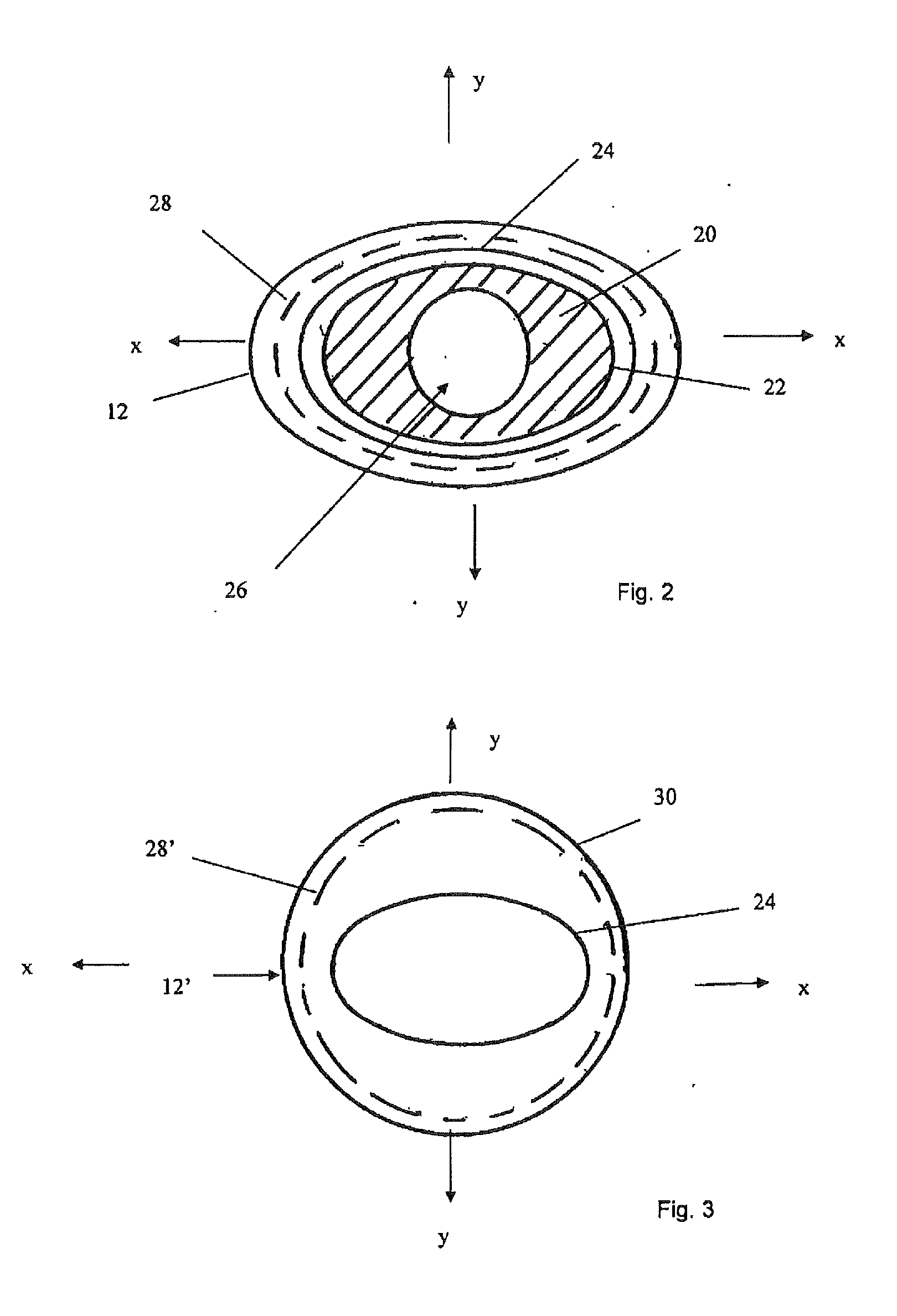
[0019]In an embodiment, the sheath element has a shape in axial cross-section which could be described as an oval ring. The carrier element is, correspondingly, oval in its outer shape (the carrier element would typically have one or more lumens within it). A structure of this nature, that is one which could be described as flattened, causes the structure to have different flexibilities in different rotational directions. In particular, when flexed about its narrower region, the assembly will be more flexible, whereas when flexed about its wider direction, it will be less flexible. It has been found that this difference in flexibilities, which is not experienced in prior art devices, can facilitate the passage of the introducer assembly through a patient's vasculature, as it enables the clinician to rotate the assembly to change its relative flexibility and thus to assist in flexing the distal end of the introducer as it passes through curves and bends in the vessels of a patient. This improved trackability is considered to be a particular
advantage of this structure.
[0020]This structure, and indeed all of the structures disclosed herein which provide different flexibilities in different radial directions of the introducer assembly, provides another important
advantage, particularly in the deployment of medical devices or instruments at or
proximate a curve in a vessel of a patient. In a curve of a vessel, the introducer assembly will tend to rotate in such a manner that it curves about its more flexible rotational orientation, in the case of an oval structure, about one of its flattened sides. Thus, in this particular example, the introducer assembly will tend to self-orient when in a curve in only two positions, equivalent to the two flattened sides of the assembly. This self-orientation can be particularly useful in the deployment of medical devices or instruments which are rotationally dependent, for instance in the deployment of fenestrated, branched or bifurcated medical devices or in the deployment of instruments which must be oriented in a particular direction. It will be appreciated that such a device would be loaded onto the introducer assembly in appropriate
rotational alignment with the non-round cross-section of the carrier element and sheath, and in such a manner that when the assembly is located at the
target site within the patient, this will self-orient such that the medical device (or instrument) located at the distal end of the assembly will likewise be oriented in the correct orientation for the deployment of that device or medical instrument. For instance, in the case of a fenestrated or branched stent graft, the fenestration or
branch would be aligned with the associated side vessel. Should the distal end of the introducer assembly be out of alignment in the vessel, this would be by 180° (in the case of an oval shape). The clinician can relatively easily correct this by twisting the proximal end of the introducer assembly to flip its distal end by 180°, thus into the correct orientation. This can considerably facilitate the deployment of rotationally dependent medical devices or
medical instruments.

