Method For the Densification of Thin Porous Substrates By Means of Vapour Phase Chemical Infiltration and Device For Loading Such Substrates

a thin porous substrate and vapour phase technology, applied in chemical vapor deposition coatings, electrical devices, coatings, etc., can solve the problems of dispersion in densification between, the extent of deformation of parts, and the deformation of parts, so as to reduce the densification gradient of substrates

Active Publication Date: 2008-06-26
SAFRAN CERAMICS SA
View PDF39 Cites 47 Cited by
  • Summary
  • Abstract
  • Description
  • Claims
  • Application Information

AI Technical Summary

Benefits of technology

[0007]An object of the invention is to provide a method that enables thin porous substrates to be densified, i.e. substrates that present thickness that is small relative to the dimensions of their main faces, such as fine parts that are plane or curved, and to enable the substrates to be loaded at high density, while simultaneously reducing densification gradients in the substrates.

Problems solved by technology

Nevertheless, using free-flow chemical vapor infiltration to densify a plurality of substrates in a common chamber leads to certain difficulties, in particular relating to the uniformity of the resulting densification.
These deposition gradients are due in particular to lack of control over the flow of reactive gas within the chamber (privileged flow paths appear), thus leading to premature depletion of reagents and consequently to dispersions in densification between those portions of the substrates that are closest to and those that are furthest from the gas admission points.
In addition to the observed lack of uniformity in deposition, the densification of thin substrates presently also requires the use of support tooling so as to limit the extent to which the parts deform as a result of the deposition gradient and / or of internal stresses in the material.
The use of such tooling penalizes the density with which the chamber can be loaded.
Nevertheless, those methods apply essentially to densifying substrates of annular shape disposed in stacks, and they are not adapted to densifying substrates presenting thin shapes.

Method used


Image

  • Method For the Densification of Thin Porous Substrates By Means of Vapour Phase Chemical Infiltration and Device For Loading Such Substrates
  • Method For the Densification of Thin Porous Substrates By Means of Vapour Phase Chemical Infiltration and Device For Loading Such Substrates
  • Method For the Densification of Thin Porous Substrates By Means of Vapour Phase Chemical Infiltration and Device For Loading Such Substrates

Examples


Embodiment Construction

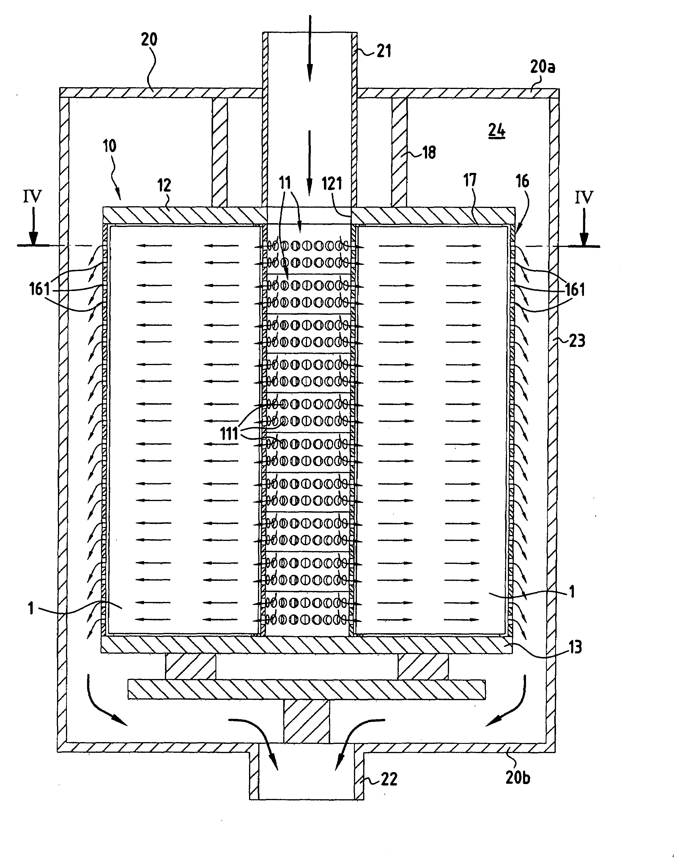
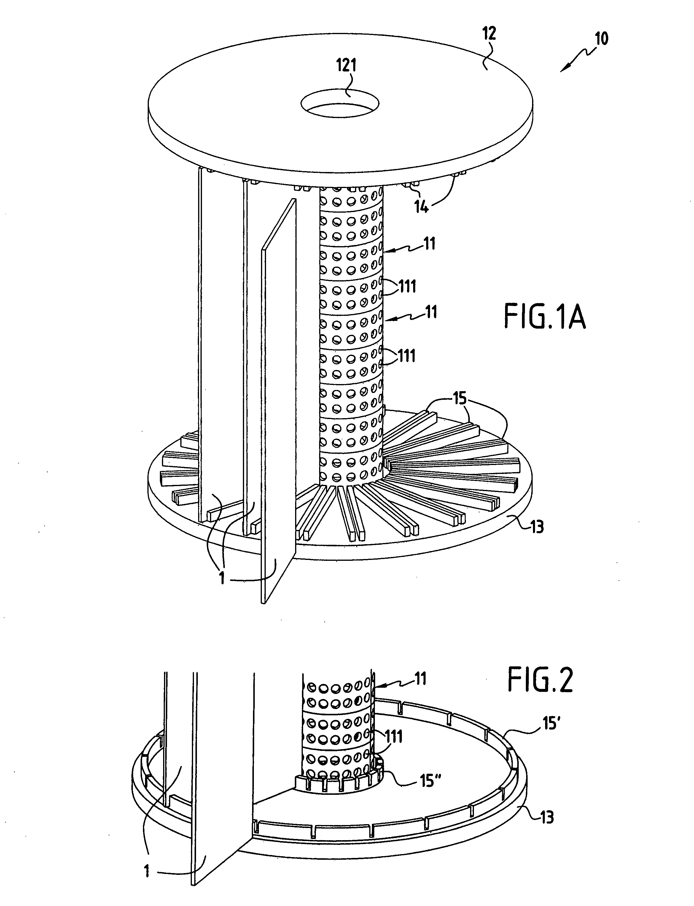
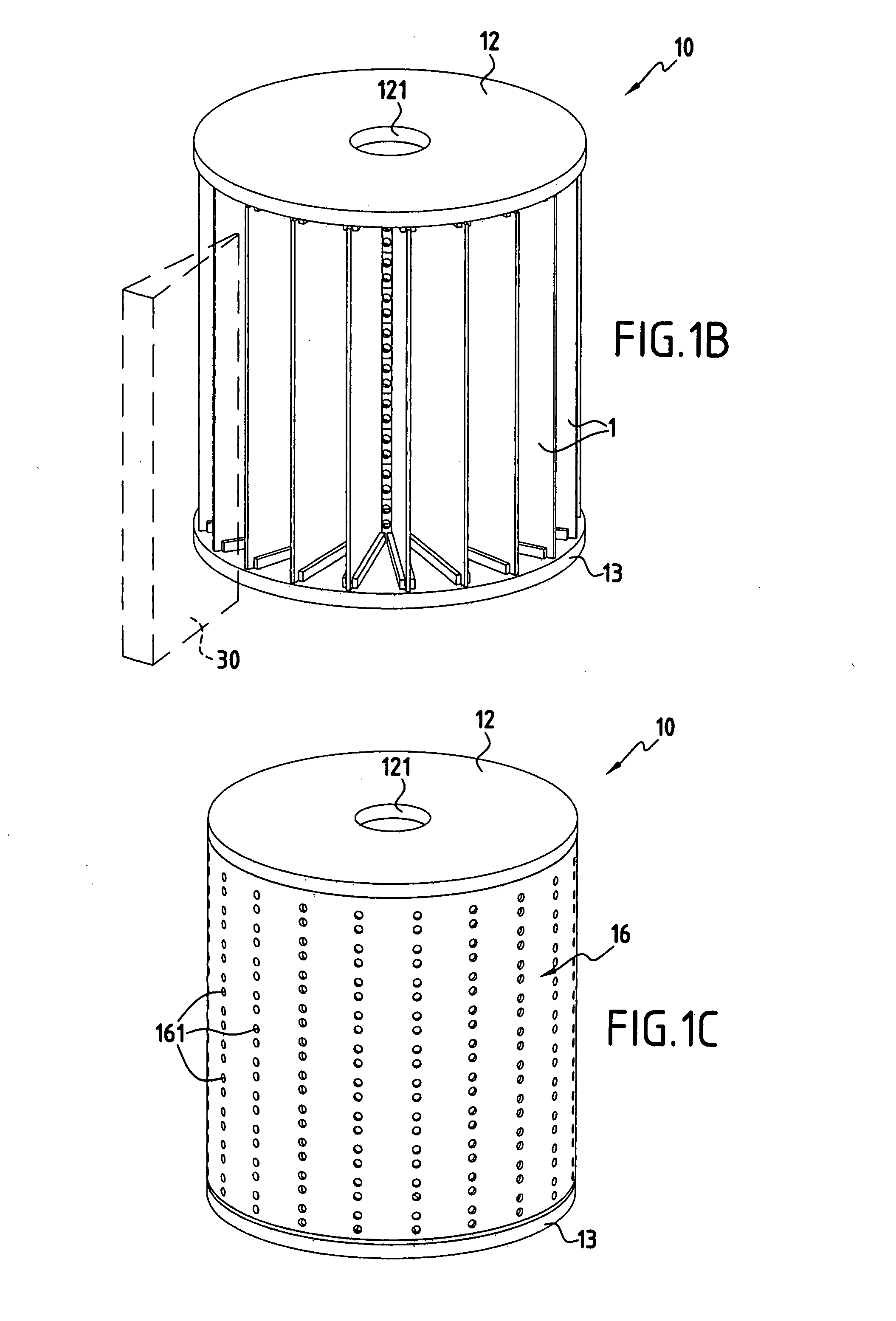
[0039]The chemical vapor infiltration method for densifying thin porous substrates in accordance with the invention makes use of specific tooling for loading purposes that are constructed and assembled as described below with reference to FIGS. 1A to 1C.

[0040]FIG. 1A shows a loading device or tool 10 at the beginning of the operation of loading substrates 1 that are to be densified, i.e. before the tooling is closed and inserted in a reaction chamber of an industrial chemical vapor infiltration installation. The tooling 10 comprises a vertical tubular duct 11 disposed between two circular plates 12 and 13. The top end of the duct 11 co-operates with a central opening 121 formed through the plate 12, and the bottom end of the duct 11 is closed by the plate 13. In a variant, the bottom end of the duct 11 could co-operate with a central opening formed through the plate 13, in particular to enable tooling devices to be superposed in a reaction chamber, as explained below.

[0041]The facin...


PUM

PropertyMeasurementUnit
thicknessesaaaaaaaaaa
refractoryaaaaaaaaaa
temperatureaaaaaaaaaa

Abstract

To densify thin porous substrates (1) by chemical vapor infiltration, the invention proposes using loading tooling (10) comprising a tubular duct (10) disposed between first and second plates (12, 13) and around which the thin substrates for densification are disposed radially. The tooling as loaded in this way is then placed inside a reaction chamber (20) in an infiltration oven having a reactive gas admission inlet (21) connected to the tubular duct (11) to enable a reactive gas to be admitted into the duct which distributes the gas along the main faces on the substrates (1) in a flow direction that is essentially radial. The reactive gas can also flow in the opposite direction, i.e. it can be admitted into the tooling (10) from its outer envelope (16) and can be removed via the duct (11).

Description

BACKGROUND OF THE INVENTION[0001]The present invention relates to the techniques of chemical vapor infiltration that are used in particular when making parts out of thermostructural composite material. The invention relates more particularly to densifying thin porous substrates by deposing a matrix, i.e. densifying substrates that present thicknesses that are relatively small compared with their main dimensions.[0002]In order to fabricate parts out of composite material, in particular parts made out of thermostructural composite material constituted by a refractory fiber preform (e.g. made of carbon or ceramic fibers) that is densified by a refractory matrix (e.g. of carbon or ceramic), it is common practice to make use of chemical vapor infiltration methods. Examples of such parts are thruster nozzles made of carbon-carbon (C—C) composite, or brake disks, in particular for airplane brakes, likewise made of C-C composite.[0003]Densifying porous substrates by chemical vapor infiltrat...

Claims


Application Information

Patent Timeline
Patent Type & Authority Applications(United States)
IPC IPC(8): C23C16/458C23C16/00
CPCC23C16/045C23C16/4587C23C16/45578
Inventor LAMOUROUX, FRANCKBERTRAND, SEBASTIENGOUJARD, STEPHANECAILLAUD, ALAINBAGILET, FRANCISMAZEREAU, STEPHANE
Owner SAFRAN CERAMICS SA
Why Eureka
Try Eureka