Method of Densifying Porous Articles

a technology of densification and porous articles, which is applied in the direction of coatings, metallic material coating processes, chemical vapor deposition coatings, etc., can solve the problems of large thermal gradients in horizontal or transverse planes, poor efficiency of conventional gas preheaters, and uneven densification of internal surfaces. achieve the effect of reducing temperature gradients, improving heat distribution, and reducing densification gradients

Active Publication Date: 2009-02-26
SAFRAN LANDING SYSTEMS
View PDF9 Cites 9 Cited by
  • Summary
  • Abstract
  • Description
  • Claims
  • Application Information

AI Technical Summary

Benefits of technology

[0014]This invention provides various ways to improve heat distribution throughout the furnace load and thus reduced the densification gradient. The present invention more particularly relates to methods of densifying porous articles or substrates (particularly, annular brake preforms), including the use of certain arrangements of porous articles which are at various stages of the manufacturing process.
[0015]A part of the present invention relates to providing partially densified substrates (I-2 parts) in the reaction chamber as a kind of passive heat distribution element, including providing I-2 parts in combination with I-1 parts being densified. The I-2 substrates help reduce temperature gradients among the stacks of I-1 and I-2 substrates being densified as explained herein. The I-2 parts are, for example, partially densified annular brake disc preforms having a bulk density between about 1.250 g / cc and about 1.770 g / cc. During densification, the I-2 parts absorb heat from the furnace and uniformly radiate the absorbed heat to surrounding preforms to thereby desirably reduce the temperature gradient in the furnace. A cycle time reduction of 12% to 30% is achievable mainly due to the temperature improvement from various loading arrangements.
[0016]The present invention is additionally applicable in the field of refurbishing worn composite brake disks made from carbon / carbon. Typically, worn brake discs are machined to remove worn surfaces before being redensified, such that the thickness of the machined part is some fraction of the thickness of the original article. In such a case, it is common to “reassemble” two or more partial thickness parts to obtain a correctly dimensioned refurbished part. Of course, redensifying such thinner machined parts is relatively easy and fast compared with thicker articles, and densification could be foreseeably completed in a single step, given correct control of the densification parameters.

Problems solved by technology

A common problem in CVI densification is that the preforms are not uniformly internally densified.
In addition, the efficiency of conventional gas preheaters may not be as good as desired.
A large thermal gradient occurs in the horizontal, or transverse, plane because of poor thermal conductivity and low thermal mass of the fiber preforms.
However, if the gas preheater is an internal device (relative to the reaction chamber) this approach reduces the useful load capacity in the furnace, which in turn reduces the number of substrates being treated.
Another problem is the formation of undesirable carbon microstructures, such as smooth laminar carbon, soot, and tar.
These type microstructures are not desirable because of their poor thermomechanical and friction properties.
These kinds of problems may be attributed to long precursor gas residence times, and to temperature variations in the deposition environment.
Finally, gas preheating can actually create undesirable effects if the temperature of the precursor gases is raised close to the reaction (i.e., deposition) temperature.
In particular, the precursor gas or gases may prematurely break down and deposit carbon soot and the like on the surface of the processing equipment or even on the exterior of the preforms.
All of these results negatively affect the efficiency of the process and the quality of the resultant articles.

Method used


Image

  • Method of Densifying Porous Articles
  • Method of Densifying Porous Articles
  • Method of Densifying Porous Articles

Examples


example 1

see FIGS. 7 and 9

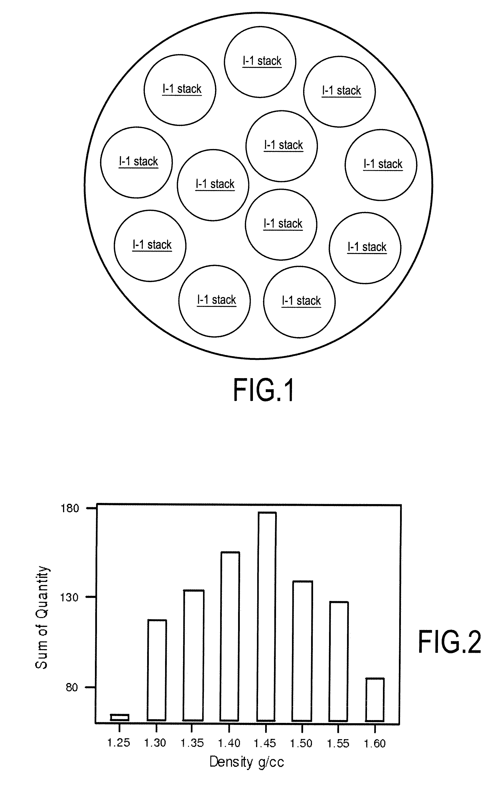
[0037]a. Approximately 1100+ / −100 substrates in a standard CVI load.[0038]b. Total load is approximately 50% I-1 parts and approximately 50% 1-2 parts.[0039]c. Cycle time could be reduced by about 12% compared with usual conventional cycles.[0040]d. Use tray 1 (on the bottom), 2, and 7 (on the top) for 1-2 parts (see FIG. 7) and tray 3, 4, 5, and 6 for I-1 parts (see FIG. 9).[0041]e. In particular, utilize the lower temperature top and bottom zones for I-2 parts (i.e., trays 1 and 7).[0042]f. Minimize the large density gradient in the full I-1 loading configuration. I-1 parts are obtained having a bulk density from 1.35 g / cc to 1.55 g / cc.

example 2

see FIGS. 11 and 13

[0043]a. Approximately 1100 (±100) substrates in a standard CVI load.[0044]b. Load consists of 50% I-1 parts and 50% 1-2 parts.[0045]c. Cycle time could be reduced by about 24%.[0046]d. Uses lateral stacks in trays 2-6 for the I-1 parts (see FIG. 9) and the rest for the 1-2 parts (see FIG. 11). See FIGS. 12 and 14.[0047]e. Provides better temperature distribution in the horizontal plane, especially for the I-1 preforms loaded in trays 2-6 at the periphery. The center I-2 stacks are used as the passive heat element in this configuration.

example 3

see FIGS. 15 and 17

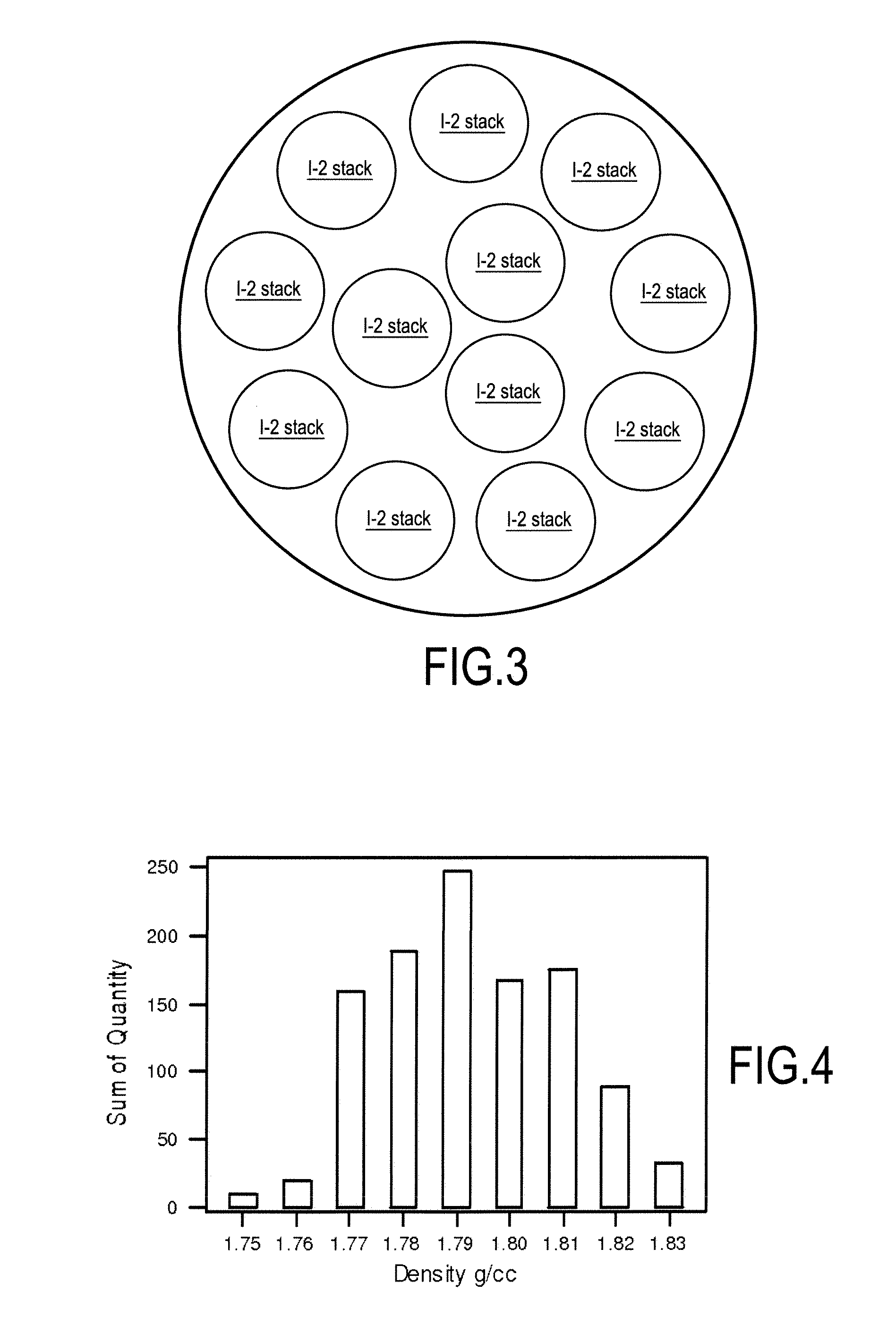
[0048]a. Approximately 1100 (±100) substrates in a standard CVI load.[0049]b. Load consists of 50% of the I-1 parts and 50% of the I-2 parts.[0050]c. Each stack on each tray comprises either all I-1 parts or all I-2 parts. Stacks of I-1 parts and stacks of I-2 parts are arranged in alternating fashion about a periphery of the tray, while the center (for example, three) stacks are either all I-1 parts (see FIG. 17) or all I-2 parts (see FIG. 15). The trays are also alternatingly stacked. For example, an arrangement according to FIG. 15 may be used as trays 1, 3, 5, and 7, while an arrangement according to FIG. 17 may be used as trays 2, 4, and 6.[0051]d. Cycle time reduction of 28% is possible.[0052]e. Provides improved temperature uniformity both in the horizontal and vertical direction, resulting in a greater number of parts attaining a desirable density. I-2 stacks are used as the passive heat element in this configuration. (See FIGS. 16 (relative to I-1 parts) ...


PUM

PropertyMeasurementUnit
densityaaaaaaaaaa
densityaaaaaaaaaa
total massaaaaaaaaaa

Abstract

The present invention describes a method of CVI densification in which particular arrangements and mixtures of undensified porous substrates and partially densified porous substrates are arranged in particular ways in order to use the thermal characteristics of the partially densified porous substrates to better distribute heat throughout a CVI furnace and thereby improve densification.

Description

[0001]This application claims the benefit of priority from U.S. Provisional Patent Application No. 60 / 863,377 filed on Oct. 29, 2006.FIELD OF THE INVENTION[0002]The invention relates to the field of carbon matrix densification made by the chemical vapour infiltration method within a carbonized carbon preform.BACKGROUND OF THE INVENTION[0003]In a conventional chemical vapour infiltration (“CVI”) process for aircraft brake manufacturing, a large number of porous substrates (frequently referred to in the art as “preforms”) are placed in a graphite reaction chamber heated by an inductive or resistive heating source to a temperature of about 900° C. to about 1000° C. A precursor gas containing one or more carbon precursors (typically hydrocarbon gases such as methane and / or propane) is admitted into the graphite reaction chamber. The precursor gas or gases are preferably preheated before entering the reaction chamber to a temperature range between about 500° C. and 950° C., and in a part...

Claims


Application Information

Patent Timeline
Patent Type & Authority Applications(United States)
IPC IPC(8): C23C16/44
CPCC04B35/632C04B35/63424C04B35/6346C04B35/63488C04B35/65C23C16/26C04B2235/608C04B2235/614C04B2235/665C23C16/045C04B35/83
Inventor CHANG, KENNYLOISY, PATRICKBAUDRY, YVAN
Owner SAFRAN LANDING SYSTEMS
Why Eureka
Try Eureka